Table of Contents
- What Is a Coaxial Connector?
- Key Specifications to Understand
- Common Coaxial Connector Types
- Connector Type Comparison
- Specialty & Niche Connectors
- How to Choose the Right Connector
- Installation Best Practices
- Common Issues & Troubleshooting
- Industry Standards & Certifications
- FAQ
- Conclusion
What Is a Coaxial Connector?
A coaxial connector terminates a coaxial cable and mates it to a device port, panel, or another cable. It maintains the cable’s characteristic impedance through the connection point while shielding the signal from external electromagnetic interference.
The connector body has two concentric conductors. The center pin (or receptacle) carries the signal. The outer shell provides the ground return path and doubles as a shield. A dielectric insulator separates the two, keeping the impedance consistent with the cable it terminates.
Coaxial cable connectors handle frequencies from DC up to millimeter-wave bands. The same basic principle applies whether you’re connecting a cable TV box at 1 GHz or a satellite earth station at 30 GHz. What changes is the precision of the machining, the dielectric material, and the coupling mechanism.
The impedance of the connector must match the cable and the equipment. Mismatch a 75-ohm F-type connector onto a 50-ohm system and you’ll get signal reflections that degrade performance. Get it right and the connector becomes electrically invisible.
Key Specifications to Understand
Before comparing connector types, you need to know what the numbers mean.
Impedance (50 Ω vs 75 Ω)
The two standards exist for historical and physical reasons. 50-ohm systems maximize power handling — that’s why broadcast, military, and cellular infrastructure use 50-ohm connectors. 75-ohm systems minimize signal attenuation per meter, which matters more for long cable runs in CATV and satellite distribution. The physical difference between a 50-ohm and 75-ohm BNC connector is subtle (the dielectric diameter changes slightly), but the electrical mismatch is real. Plug a 50-ohm connector into a 75-ohm system and you’ll see a VSWR of roughly 1.5:1 — about 4% reflected power. Acceptable for test bench work, unacceptable for precision measurement.
Frequency Range
Every connector type has an upper frequency limit. Above that limit, the connector geometry starts supporting higher-order propagation modes that sap signal energy. BNC tops out around 4 GHz. SMA handles 18 GHz in its standard form and 26.5 GHz in precision versions. N-type reaches 11 GHz in common grades and 18 GHz in precision grades. Operating a connector beyond its rated frequency doesn’t cause catastrophic failure — it causes gradual, hard-to-diagnose performance degradation.
VSWR (Voltage Standing Wave Ratio)
VSWR measures how much signal reflects back from the connector instead of passing through. A perfect match is 1.0:1. A good BNC might measure 1.2:1 at 1 GHz. A precision 3.5mm connector might hold 1.05:1 at 26.5 GHz. Every connector adds a small impedance bump. The art of connector design is making that bump as small as possible across the operating band.
Insertion Loss
This is the signal power lost as it passes through the connector — typically 0.1 to 0.3 dB per mated pair at rated frequency. Doesn’t sound like much until you have six connectors in a signal path and suddenly you’ve lost 1.5 dB. That’s 30% of your signal gone before it reaches the antenna. In receiver front-ends, every tenth of a dB matters.
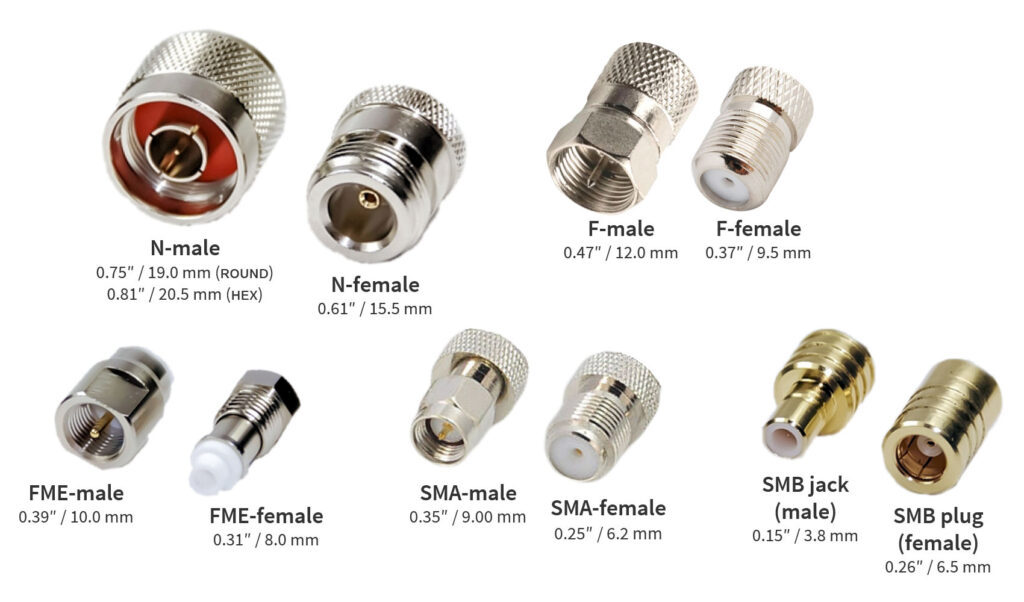
Gender (Male vs Female, Plug vs Jack)
A male connector has a center pin. A female connector has a center receptacle. The outer shell reverses: the male typically has a rotating coupling nut (on threaded types), while the female has fixed external threads. Panel-mount connectors are usually female to protect the center contact from damage.
Reverse Polarity (RP)
Reverse polarity connectors swap the pin and receptacle while keeping the same shell geometry. The RP-SMA has a female body with a male center pin. The RP-TNC has a male body with a female center receptacle. The FCC mandated these for Part 15 WiFi equipment to prevent consumers from attaching high-gain antennas to devices that weren’t certified for them. In practice, it created a parallel universe of connectors that look identical but don’t mate with their standard counterparts.
Coupling Mechanisms
Threaded couplings (SMA, N-type, TNC, F-type) provide the most secure connection and best electrical performance. Bayonet couplings (BNC) trade some performance for speed — quarter-turn connect/disconnect. Snap-on couplings (SMB, MCX) prioritize density and quick connection over ruggedness. Push-on (RCA) is adequate for audio and baseband video.
Common Coaxial Connector Types
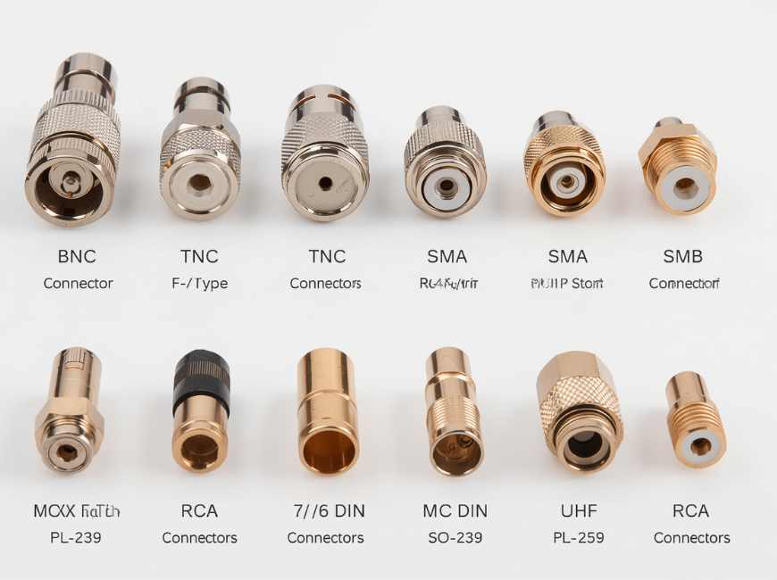
BNC Connector
The BNC (Bayonet Neill-Concelman) connector emerged from military work in the 1940s. Paul Neill (of N-type fame) and Carl Concelman (of C-type fame) combined a bayonet locking mechanism with a compact form factor. The result became one of the most widely used RF connectors in history.
Key specs: 50 Ω and 75 Ω versions available. Rated to 4 GHz in standard form, with precision versions reaching 10 GHz. The bayonet coupling uses two external studs on the female that lock into slots on the male’s rotating ring. Quarter-turn to mate or unmate.
Typical applications: CCTV and analog video, test and measurement equipment, broadcast studio patch panels, older Ethernet (10BASE2), oscilloscope probes, RF signal generators.
Pros: Fast connect/disconnect, mechanically robust, widely available, inexpensive. Cons: Limited frequency range, not weatherproof without a boot, bayonet can loosen under vibration.
TNC Connector
The TNC (Threaded Neill-Concelman) takes the BNC internal geometry and replaces the bayonet with a 7/16-28 threaded coupling. That single change extends the usable frequency range to 11 GHz in standard versions and 18 GHz in precision versions.
Key specs: 50 Ω standard, 75 Ω available. Threaded coupling. Rated to 11 GHz (standard), 18 GHz (precision). More resistant to vibration than BNC.
Typical applications: Cellular base station antennas, aviation electronics, radar systems, outdoor wireless infrastructure. The threaded design makes it inherently more weather-resistant than BNC.
Pros: Higher frequency than BNC, vibration-resistant, weather-resistant with proper sealing. Cons: Slower to connect than BNC, larger than SMA, less common in consumer equipment.
F-Type Connector
The F-type connector is the workhorse of consumer RF distribution. It uses the cable’s solid center conductor as its own center pin, which keeps the design simple and cheap but puts the burden of reliability on cable preparation quality.
Key specs: 75 Ω. Threaded coupling. Rated to 1 GHz in standard form, with compression versions reaching 3 GHz. Compatible with RG6, RG59, and RG11 coaxial cables.
Typical applications: Cable television, satellite TV (DBS), cable modems, antenna distribution, MoCA home networking.
Pros: Inexpensive, simple to install, good electrical performance when properly terminated. Cons: The exposed center conductor corrodes in outdoor installations without weather boots. Threads can strip on cheap connectors. Not suitable for frequent connect/disconnect cycles.
N-Type Connector
Paul Neill designed this connector at Bell Labs in the 1940s, and it remains a standard for medium-power RF applications. The N-type connector uses a 5/8-24 threaded coupling with a silicone rubber gasket that provides weather sealing without additional boots.
Key specs: 50 Ω standard, 75 Ω available. Threaded coupling with integral gasket. Rated to 11 GHz (standard), 18 GHz (precision). Handles power levels up to several hundred watts at lower frequencies.
Typical applications: Cellular base station feedlines, broadcast transmitters, antenna systems, RF test equipment, WiFi access points with external antennas, two-way radio repeaters.
Pros: Weatherproof by design, excellent power handling, wide frequency range, durable. Cons: Larger and heavier than SMA, more expensive than BNC or F-type, requires a torque wrench for optimal performance.
SMA Connector
The SMA connector (SubMiniature version A) packs precision into a compact package. A 1/4-36 threaded coupling and stainless steel construction make it the default choice for microwave applications up to 18 GHz, with precision variants reaching 26.5 GHz.
Key specs: 50 Ω. 1/4-36 threaded coupling. Rated to 18 GHz (standard stainless steel), 26.5 GHz (precision). Designed for 500 mating cycles minimum.
Typical applications: GPS receivers, WiFi and cellular antennas, microwave radios, spectrum analyzers, vector network analyzers, satellite communications.
Pros: Compact, excellent high-frequency performance, wide industry adoption, precision versions available. Cons: Limited mating cycles compared to N-type, small threads easily cross-threaded, not designed for high power, requires torque wrench for repeatable measurements.
SMB Connector
The SMB (SubMiniature version B) uses a snap-on coupling instead of threads. It’s smaller than SMA and designed for quick connections in tight spaces where you can’t swing a wrench.
Key specs: 50 Ω and 75 Ω versions. Snap-on coupling. Rated to 4 GHz. Smaller than SMA.
Typical applications: Telecommunications equipment, industrial controls, automotive electronics, internal board-to-board RF connections.
Pros: Quick connect/disconnect, compact, good for high-density panels. Cons: Lower frequency limit than SMA, snap-on coupling less secure than threaded, not weatherproof.
MCX and MMCX Connectors
MCX (Micro Coaxial) and MMCX (Micro-Miniature Coaxial) shrink the snap-on concept further. MCX is 30% smaller than SMB. MMCX is 45% smaller than MCX. Both use snap-on coupling.
Key specs: 50 Ω. MCX rated to 6 GHz, MMCX to 6 GHz. MMCX allows 360° rotation after mating, which simplifies cable routing in tight enclosures.
Typical applications: GPS antennas, portable wireless devices, PC card wireless adapters, medical telemetry, drone video transmitters.
Pros: Extremely compact, MMCX rotatable joint, good for space-constrained designs. Cons: Limited mating cycles (typically 500), not weatherproof, small size makes field repair difficult.
7/16 DIN Connector
The 7/16 DIN connector was developed in Germany for high-power cellular base station applications. The name comes from the metric thread dimensions: 7 mm inner conductor diameter, 16 mm outer conductor diameter.
Key specs: 50 Ω. Threaded coupling (M29 x 1.5). Rated to 7.5 GHz. Handles average power levels of 2,700 W at 1 GHz. IP68 rated when properly mated.
Typical applications: Cellular base station antenna connections, broadcast transmitter outputs, high-power combiners and filters.
Pros: Exceptional power handling, weatherproof, low PIM (Passive Intermodulation), robust mechanical design. Cons: Large and heavy, expensive, overkill for low-power applications.
RCA Connector
The RCA connector (Radio Corporation of America, the company that popularized it in the 1940s) handles baseband audio and video. It’s not a precision RF connector, but it carries composite video signals up to about 6 MHz and belongs in any complete connector discussion.
Key specs: Not impedance-controlled in consumer versions (typically around 75 Ω in practice). Push-on coupling. Rated for audio and baseband video frequencies.
Typical applications: Consumer audio, composite and component video, S/PDIF digital audio, subwoofer connections.
Pros: Ubiquitous, inexpensive, color-coded. Cons: Not impedance-controlled, no locking mechanism, poor shielding, not suitable for RF above baseband.
UHF Connector (PL-259/SO-239)
The UHF connector dates to the 1930s and was originally designed for “Ultra High Frequency” — which at the time meant 30-300 MHz. The PL-259 is the male plug; the SO-239 is the female socket. Despite its name, this connector is not constant-impedance and performs poorly above 300 MHz.
Key specs: Nominally 50 Ω but not constant-impedance across frequency. Threaded coupling (5/8-24). Practical limit around 300 MHz. Handles high power at HF/VHF.
Typical applications: Amateur radio HF/VHF transceivers, CB radio, marine VHF, some older commercial two-way radio equipment.
Pros: Rugged, high power handling, easy to solder in the field, inexpensive. Cons: Not constant-impedance, poor performance above 300 MHz, bulky, not weatherproof without additional sealing.
Connector Type Comparison
| Connector | Impedance | Max Frequency | Coupling | Typical Applications | Relative Cost |
|---|---|---|---|---|---|
| BNC | 50/75 Ω | 4 GHz | Bayonet | CCTV, test equipment, video | $ |
| TNC | 50 Ω | 11 GHz | Threaded | Cellular, aviation, radar | $$ |
| F-Type | 75 Ω | 3 GHz | Threaded | CATV, satellite, cable modem | $ |
| N-Type | 50 Ω | 11 GHz | Threaded | Base stations, broadcast, WiFi | $$ |
| SMA | 50 Ω | 18 GHz | Threaded | GPS, microwave, test equipment | $$ |
| SMB | 50/75 Ω | 4 GHz | Snap-on | Telecom, industrial, automotive | $$ |
| MCX | 50 Ω | 6 GHz | Snap-on | GPS, portable devices | $$ |
| MMCX | 50 Ω | 6 GHz | Snap-on | Mobile devices, medical | $$ |
| 7/16 DIN | 50 Ω | 7.5 GHz | Threaded | Cellular base stations, broadcast | $$$ |
| RCA | ~75 Ω | 6 MHz | Push-on | Consumer audio/video | $ |
| UHF | ~50 Ω | 300 MHz | Threaded | Amateur radio, CB, marine | $ |
Specialty & Niche Connectors
Several connector types serve specific niches that the mainstream options don’t cover well.
QMA — A quick-lock variant of SMA introduced in 2003. Replaces the threaded coupling with a snap-on mechanism that maintains SMA’s electrical performance. Useful in high-density panel applications where you can’t access individual connectors with a torque wrench. Limited adoption outside telecom infrastructure.
FME — Designed to fit through conduit and tight routing paths. The connector body is small enough to pass through a 10 mm hole. Common on mobile antennas and vehicle installations where the cable must route through firewalls or trunk grommets. Compatible with RG58 cable.
PAL — The standard antenna connector for European and Asian consumer electronics. Rare in North America. Similar in concept to F-type but with a push-on coupling. Used on TVs, set-top boxes, and FM receivers throughout Europe.
TS-9 — An ultra-miniature connector found on USB TV tuners, portable DVB-T receivers, and some older mobile phones. Mates with LMR-100 and RG-174 micro-coax. Fragile and not designed for frequent cycling.
NMO (New Motorola Mount) — A mounting system rather than a cable connector. NMO mounts thread into a 3/4-inch hole on a vehicle body panel and accept interchangeable antenna whips. The connector sits flush with the mounting surface. Standard on police cruisers, utility trucks, and commercial fleet vehicles.
DIN 1.0/2.3, 4.1/9.5 (Mini-DIN), and 4.3/10 — The DIN 4.1/9.5 (often called Mini-DIN) was designed as a smaller alternative to 7/16 DIN for cellular applications. The newer DIN 4.3/10 reduces size further while improving PIM performance and eliminating the coupling nut entirely with a push-pull mechanism. The 4.3/10 is rapidly becoming the standard for 5G base station antenna connections.
QN — A quick-disconnect version of the N-type connector. Maintains N-type electrical performance with a push-pull locking mechanism instead of threads. Used where N-type performance is needed but frequent reconfiguration makes threaded connections impractical.
How to Choose the Right Connector
Start with the electrical requirements, then narrow by mechanical and environmental constraints.
Step 1: Match the impedance. If your system is 50 ohms, eliminate all 75-ohm connectors immediately. The exception is when you’re designing a matching network that accounts for the mismatch — but that’s rare outside specialized RF engineering.
Step 2: Check the frequency. Take your system’s maximum operating frequency and add 20% margin. If you’re operating at 5.8 GHz, a BNC (rated to 4 GHz) won’t cut it. An SMA or TNC will. Don’t rely on a connector’s “typical” performance above its rated frequency.
Step 3: Assess the environment. Outdoor installations need weather resistance. Threaded connectors with integral gaskets (N-type, 7/16 DIN) handle moisture better than bayonet or snap-on types. For marine or coastal environments, consider connector body materials and plating — salt spray destroys nickel-plated brass in months. Stainless steel bodies with gold-plated center contacts survive much longer.
Step 4: Consider the mechanical requirements. How many mating cycles? Will the connection experience vibration? Do you need to connect and disconnect frequently? BNC is good for frequent cycling. SMA is not — cross-thread a stainless SMA once and both connectors are scrap. For vehicle-mounted equipment, threaded connectors with positive locking outperform snap-on types.
Step 5: Factor in cable compatibility. Not every connector is available for every cable type. RG58, RG174, RG6, RG213, LMR-400 — each has a different diameter and requires a connector designed for that specific cable. For custom applications, companies like Ouketech provide custom coaxial cable assemblies built to your exact specifications, eliminating the guesswork of field termination.
Step 6: Budget realistically. An N-type connector costs more than a BNC, but replacing corroded BNCs on a rooftop installation every two years costs more than doing it right the first time. For industrial environments where downtime is expensive, the connector is the cheapest part of the system. Custom cable assemblies with factory-terminated connectors eliminate field installation variables and often pay for themselves in reduced failure rates.
Quick Selection Checklist
- Impedance matches system (50 Ω or 75 Ω)
- Frequency rating exceeds maximum operating frequency by ≥20%
- Coupling mechanism appropriate for environment (threaded for outdoor/vibration)
- Connector plating compatible with environmental exposure
- Cable diameter matches connector design
- Mating cycle rating exceeds expected lifetime cycles
- Reverse polarity check (standard vs RP) if used with WiFi/consumer wireless
- Connector gender matches panel/device port
Installation Best Practices
Cable Preparation
The most common cause of connector failure is poor cable prep. Use a proper coaxial cable stripper — not a utility knife. The strip dimensions (center conductor exposure, dielectric length, outer jacket removal) are specific to each connector type. A 1 mm error in the dielectric strip length on an SMA connector will change the impedance at the transition point.
For industrial wire harness applications where multiple coaxial lines run in the same bundle, consistent strip lengths across all terminations become critical for uniform electrical performance.
Crimp vs Clamp vs Solder
Crimp connectors use a hexagonal or round compression die to secure the ferrule around the cable braid. When done with the correct die set, crimp connections provide consistent, gas-tight contact. They’re the standard for production environments.
Clamp connectors use a threaded nut to compress a tapered ferrule. They’re reusable and field-serviceable but require more skill to assemble correctly.
Solder center pins provide the lowest contact resistance but require skill and the right soldering iron temperature. Too hot and you melt the dielectric. Too cold and you get a cold joint that will fail under thermal cycling. Most modern connectors use crimp or press-fit center pins to eliminate soldering variables.
Torque Wrench Usage
Threaded RF connectors need specific torque values for optimal electrical performance. SMA: 0.8-1.1 N·m (7-10 in·lb). 3.5mm and 2.92mm precision connectors: 0.8 N·m (7 in·lb). N-type: 1.4-1.7 N·m (12-15 in·lb). Over-torquing deforms the center conductor and degrades VSWR. Under-torquing leaves a gap that creates an impedance discontinuity. A calibrated torque wrench is not optional for precision work.
Weatherproofing
For outdoor connections, use self-amalgamating tape (butyl rubber tape that fuses to itself) wrapped from the cable jacket onto the connector body, overlapping by 50% on each wrap. Cover with a layer of UV-resistant electrical tape. For coastal or high-humidity environments, add a weatherproof boot over the entire assembly. N-type connectors with integral gaskets still benefit from additional taping in permanent outdoor installations.
Inspection After Installation
Test every connection with a VSWR meter or vector network analyzer if available. A sudden VSWR spike at a specific frequency often indicates a connector problem. For field installations without test equipment, at minimum check that the center pin is straight, the coupling is tight, and there’s no visible gap between the connector and the device port.
Common Issues & Troubleshooting
Intermittent Signal Loss
The connection works when you wiggle the cable and fails when you let go. This almost always points to a broken center conductor solder joint or a loose crimp ferrule. Replace the connector. Field repairs on intermittent connectors rarely hold up.
High VSWR After Installation
If a newly installed connector shows poor VSWR, check the strip dimensions first. A center conductor that’s too long bottoms out in the mating connector and pushes the dielectric back. Too short and you get a capacitive gap. Either way, the impedance bump reflects signal. Re-terminate with correct dimensions.
Corrosion and Oxidation
White or green powder on connector bodies means the plating has failed and the base metal (usually brass) is corroding. Nickel-plated connectors in outdoor environments are particularly susceptible. Gold-plated center contacts resist oxidation better than silver, but silver offers slightly lower contact resistance when clean. For automotive wiring harness applications where connectors face temperature extremes, vibration, and road salt, connector plating selection directly impacts long-term reliability.
Loose Connections
Bayonet couplings (BNC) can loosen over time as the locking slots wear. Snap-on connectors (SMB, MCX) lose retention force after repeated cycling. If a BNC connector rotates freely or a snap-on connector pulls off with minimal force, replace it. The wear is in the spring fingers, not something you can tighten.
Impedance Mismatch Symptoms
Using a 50-ohm connector in a 75-ohm system (or vice versa) causes ghosting on analog video, bit errors on digital signals, and reduced range on RF links. The physical difference between 50-ohm and 75-ohm BNC connectors is subtle — the 75-ohm version has a slightly smaller dielectric diameter and often lacks the dielectric completely around the center contact. If you’re unsure which you have, measure the VSWR with a known-good load.
When to Replace vs Repair
Replace the connector if: the center pin is bent, the dielectric is cracked or discolored, the threads are damaged, the plating is worn through to base metal, or the connector has been exposed to water ingress. A connector costs a few dollars. The diagnostic time you’ll spend chasing an intermittent problem costs far more.
Industry Standards & Certifications
MIL-PRF-39012 — The primary U.S. military specification for RF connectors. Covers BNC, TNC, N-type, SMA, and others. Defines dimensional requirements, electrical performance, environmental testing, and quality assurance provisions. A connector meeting MIL-PRF-39012 has passed salt spray, thermal shock, vibration, and durability testing.
MIL-STD-348 — Defines the interface dimensions for RF connectors used in military equipment. If two connectors from different manufacturers both comply with MIL-STD-348, they will mate correctly regardless of brand.
MIL-DTL-17 — Covers flexible and semi-rigid coaxial cables rather than connectors, but connector manufacturers reference it for cable compatibility specifications.
IEEE 287 — The standard for precision coaxial connectors used in calibration and measurement. Covers 7 mm, 3.5 mm, 2.92 mm, and other laboratory-grade connector types. These connectors achieve VSWR below 1.05:1 across their rated bandwidth and are used primarily in metrology labs and calibration facilities.
IEC 61169 — The international standard series covering RF connectors. Part numbers correspond to connector types (IEC 61169-8 covers BNC, IEC 61169-16 covers N-type, IEC 61169-32 covers SMA). European and Asian manufacturers typically reference IEC standards rather than MIL specifications.
ISO 9001 / IATF 16949 — Quality management system certifications. ISO 9001 applies broadly. IATF 16949 is specific to automotive supply chains. A connector manufacturer with IATF 16949 certification has demonstrated process control suitable for automotive production — relevant if you’re sourcing connectors for vehicle applications.
FAQ
Q: Can I use a 50-ohm BNC connector with 75-ohm equipment?
Physically, yes — they mate. Electrically, you’ll get a VSWR of about 1.5:1, meaning roughly 4% of your signal reflects back. For analog CCTV video at baseband frequencies, you probably won’t notice. For HD-SDI digital video at 1.5 Gbps, the bit errors will make the signal unusable. Use the correct impedance.
Q: What’s the difference between SMA and RP-SMA?
RP-SMA reverses the gender of the center contact while keeping the same outer shell. Standard SMA male has a center pin and a threaded barrel with internal threads. RP-SMA male has a center receptacle and a threaded barrel with internal threads. They look almost identical but won’t mate with each other. RP-SMA exists because the FCC required unique connectors on Part 15 WiFi equipment.
Q: How do I weatherproof an outdoor coaxial connection?
Wrap the connection with self-amalgamating butyl rubber tape, starting on the cable jacket and extending past the connector body onto the device port. Overlap each wrap by 50%. Cover with UV-resistant electrical tape. For permanent installations, add a weather boot. N-type connectors with integral gaskets provide a good first line of defense but still benefit from taping in exposed locations.
Q: Why does my F-type connector keep loosening?
F-type connectors rely on the cable’s center conductor as the pin. Thermal cycling causes the center conductor to expand and contract, which can back the connector off the threads. Use compression-type F connectors rather than crimp-type, and tighten them to the manufacturer’s specified torque (typically finger-tight plus a quarter turn with a wrench). Don’t over-tighten — you’ll flare the female port and ruin the connection.
Q: How many times can I mate and unmate an SMA connector?
Standard SMA connectors are rated for 500 mating cycles minimum. In practice, the threads start showing wear after 100-200 cycles if you’re not using a torque wrench. Precision SMA connectors (3.5mm, 2.92mm) are rated for 5,000 cycles but cost significantly more. Always use a torque wrench and clean the mating surfaces between connections.
Q: What connector should I use for a 5G small cell installation?
DIN 4.3/10 is becoming the standard for 5G infrastructure. It offers better PIM performance than 7/16 DIN in a smaller package, and the push-pull coupling eliminates the need for torque wrenches in tight spaces. N-type remains common on existing installations, but new deployments are shifting toward 4.3/10.
Q: Can I solder a connector that was designed for crimping?
You can, but you shouldn’t. Crimp connectors are designed with specific ferrule dimensions that assume compression, not solder flow. Solder wicks up the braid and creates a stiff point that concentrates mechanical stress. If the connector gets hot enough during operation, the solder can soften. Use the termination method the connector was designed for.
Conclusion
Coaxial cable connectors look simple from the outside. The differences between a BNC and a TNC come down to a coupling mechanism. The difference between a good installation and a bad one comes down to strip dimensions measured in millimeters and torque values measured in inch-pounds.
The right connector for your application depends on frequency, impedance, environment, and mechanical requirements. A $2 F-type connector works perfectly for cable TV at 1 GHz. That same connector on a 5.8 GHz wireless link would be a disaster. Match the connector to the job.
For applications that demand reliability beyond off-the-shelf solutions, custom cable assemblies with factory-terminated connectors remove the variables of field installation. When your coaxial connections are part of a larger system — whether it’s an automotive wiring harness, an industrial wire harness, or a custom RF distribution panel — getting the connector selection right at the design stage saves rework, downtime, and field failures.