

A 4-pin electrical connector may carry power, signals, data, or a combination of all three. The contact count alone does not identify the connector: an M12 sensor plug, a Deutsch DT automotive housing, a JST board connector, and a 4-way trailer plug can all have four contacts while differing in pitch, keying, sealing, current rating, and termination method.
For engineers and procurement teams, the practical question is not simply “Which 4-pin connector is this?” It is whether the complete connection will suit the electrical load, mating interface, operating environment, installation process, and production plan. This guide explains the main connector families and shows what to specify when requesting a custom 4-pin cable assembly, prototype, or production quotation.
Safety note: Pin assignments and ratings vary by connector series, manufacturer, and application. Treat the examples below as identification guidance. Confirm the exact part-number drawing, equipment documentation, and approved pinout before wiring or ordering.
Quick Comparison of Common 4-Pin Connector Types
| Connector family | How to recognize it | Typical project use | What a buyer should verify |
|---|---|---|---|
| Deutsch DT / sealed automotive | Rectangular housing, positive latch, secondary lock | Vehicles, mobile equipment, outdoor machinery | Exact housing and contact part numbers, seal, wire gauge, keying, temperature and fluid exposure |
| EFI sensor connector | Compact molded or clipped housing, often supplied as a pigtail | Sensors, actuators, engine-management systems | Mating sensor, terminal system, pinout, wire insulation and strain relief |
| M8 / M12 circular | Circular body with threaded coupling and coding key | Sensors, factory automation, industrial equipment | A/B/D coding, male/female orientation, straight/right-angle exit, shield, IP rating and cable jacket |
| JST XH / PH and similar wire-to-board | Small white housing with friction latch | Electronics, controls, compact equipment | Series, pitch, genuine/equivalent part requirement, contact plating, wire size and insertion direction |
| 4-pin peripheral power | Large white inline housing with four round contacts | Legacy computer and accessory power | Mating compatibility, circuit load and wire gauge |
| 4-pin CPU/EPS | Black 2 x 2 keyed housing with latch | Motherboard power | Keying, equipment compatibility and power-supply documentation |
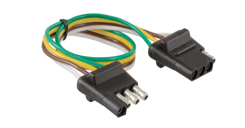
| 4-way trailer | Flat row or circular pattern, commonly color-coded | Trailer lighting | Vehicle/trailer standard, corrosion protection, ground path and circuit load |
| 4-position terminal block | Four screw or clamp positions | Control panels and field wiring | Pitch, current/voltage rating, conductor range, mounting and required approvals |
This comparison is a starting point, not a cross-reference. Two connectors that look similar may use incompatible terminals, keys, seals, or pitches.

What Is a 4-Pin Electrical Connector?
A 4-pin connector has four conductive positions arranged in one row, a 2 x 2 matrix, or a circular pattern. The four circuits can be assigned in many ways, including:
- supply voltage, ground, and two signal lines;
- two power contacts and two returns;
- power, ground, control, and feedback;
- four independent switching or lighting circuits; or
- a differential data pair plus power and ground.
There is no universal 4-pin connector pinout. Color conventions can help during identification, but they do not replace a drawing or electrical test. Before approving an OEM 4-pin wire harness, define the view orientation as well as the pin numbers—for example, “mating-face view of the female housing”—so the supplier does not mirror the circuit assignment.
Key Specifications to Check Before You Buy
Connector series, pitch, and keying
Identify the manufacturer series or an approved equivalent whenever possible. For small wire-to-board connectors, measure the center-to-center pitch; a 2.0 mm housing will not mate with a 2.5 mm header. For circular connectors, record the thread size, coding, contact arrangement, and key position. For automotive housings, include clear photos of the mating face, latch, wire-entry side, markings, and secondary lock.
Electrical load
Confirm rated current and voltage from the exact connector and terminal datasheets. Also review conductor size, contact resistance, ambient temperature, number of simultaneously loaded circuits, bundling, and permissible temperature rise. A catalog rating should not be applied automatically to every cable construction or installation.
Wire and cable construction
A quotation for a 4-pin connector with custom wire length should define conductor gauge, stranding, insulation, color, length and tolerance. Add jacket material, shielding, drain wire, twisted-pair construction, flex requirement, and flame or chemical-resistance requirements when relevant.
Environmental protection
“Waterproof” is incomplete without a specified test condition. A 4-pin IP67 connector cable assembly normally depends on the correct mating connector, seals, cable diameter, assembly process, and installation. If the project calls for IP68 or washdown exposure, provide the required depth, duration, temperature, chemicals, and mating state for engineering review rather than relying on the IP number alone.
Mechanical interface
Specify male or female, plug or receptacle, panel mount or inline, straight or right-angle, latch or thread, mating frequency, pull/strain requirement, bend direction, and available installation space. A right connector with the wrong cable-exit orientation can still be unusable in the final equipment.
Major 4-Pin Connector Families
Automotive 4-Pin Connectors
Sealed automotive families such as Deutsch DT-style connectors use positive locking features, secondary locks, individual wire seals, and crimp contacts. They are common in vehicles, agricultural machines, construction equipment, and other vibration-prone environments.
A 4-pin Deutsch connector wire harness RFQ should identify the exact housing, wedge lock, terminals, wire seals, conductor size, circuit assignment, branch length, protective covering, and expected environment. If the project uses a substitute or cross-reference, request a mating and terminal-compatibility review before sample approval.
Compact EFI-style connectors are also used for sensors and actuators, but their pinouts are device-specific. Do not copy a VCC-ground-signal-shield pattern from another sensor without checking the equipment documentation.
For vehicle programs, see OUKETECH's automotive wiring harness manufacturing page for related assembly considerations.
Industrial 4-Pin M8 and M12 Connectors
M8 and M12 circular connectors are widely used for sensors, actuators, control equipment, and industrial networking. A common 4-pin M12 A-coded sensor convention uses brown, white, blue, and black conductors, but the device documentation remains decisive. Other codings have different intended interfaces and keying.
When sourcing a 4-pin M12 cable assembly, specify:
- M8 or M12 size and coding;
- male/female and mating-face orientation;
- single-ended, double-ended, or blunt-cut configuration;
- straight or right-angle connector body;
- cable length, conductor size, jacket and flex requirement;
- shielded or unshielded construction;
- required ingress-protection test condition; and
- labeling, packaging and test-record requirements.
If standard field-wireable hardware does not suit the application, a custom overmolded 4-pin cable can add strain relief and a controlled cable exit. Overmolding material, adhesion, bend geometry and environmental requirements must still be defined. Learn more about overmolded cable assemblies and industrial wire harnesses.
JST and Other 4-Pin Wire-to-Board Connectors
JST is a manufacturer, not a single connector standard. XH, PH, ZH, SH and other families differ in pitch, height, latch geometry, contacts, and compatible wire range. Similar-looking products from other brands may not be drop-in substitutes.
For a 4-pin JST cable assembly, provide the full connector series or part number, mating header, wire gauge, wire color sequence, contact plating if controlled, insertion direction, finished length, and pull-test or retention requirement. A photo alone is rarely enough for repeat production.
4-Pin Power and Computer Connectors
The legacy 4-pin peripheral power connector typically carries +12 V, two grounds, and +5 V, while a 2 x 2 CPU/EPS connector typically supplies two +12 V and two ground circuits. The housings are not interchangeable. Use the power-supply and motherboard documentation, because system compatibility and permitted loading cannot be inferred from pin count.
4-Way Trailer Connectors
North American 4-way flat trailer wiring commonly assigns green to right turn/brake, yellow to left turn/brake, brown to running lights, and white to ground. Regional practices and modified vehicles can differ, so verify functions electrically before connecting. Where electric brakes, reverse lights, or auxiliary power are required, a higher-pole connector may be more appropriate.
Four-Position Terminal Blocks
Terminal blocks provide four independent clamping positions rather than a plug-and-socket interface. Check conductor range, torque, pitch, current and voltage ratings, mounting method, touch protection, and any required approvals. The circuit assignment is determined by the equipment design.
How to Identify an Unknown 4-Pin Connector
1. Photograph every useful view
Capture the mating face, wire-entry side, latch, key, panel flange, markings, and the connector beside a ruler. Include the mating half if available. This gives a 4-pin connector supplier enough information to narrow the family without guessing from one front view.
2. Measure the interface
Record pin pitch, housing width and height, thread diameter, contact diameter, and key position. For board connectors, measure center-to-center rather than the outside edges of adjacent pins.
3. Record termination and mounting
Note whether the assembly uses crimp, solder, IDC, screw clamp, PCB mount, inline cable-to-cable, or panel mount termination. Also record the wire gauge and cable outside diameter.
4. Confirm the pinout safely
Disconnect power and follow the equipment manufacturer's procedure. Use approved drawings and continuity checks to trace each circuit. Label the reference view on the pinout table. Never assume that connector gender, wire color, or a visually similar internet diagram proves the circuit assignment.
From Connector Selection to a Custom 4-Pin Cable Assembly
Buying loose connectors and sourcing a finished assembly are different tasks. A custom 4-pin connector cable combines the connector pair with wire or cable, contacts, seals, splices, branches, labels, protection, and defined workmanship or test requirements.
A build-to-print project may begin with a released drawing and BOM. Earlier projects may start from a mating-device part number, an existing sample, marked photos, or a draft pinout. In either case, the manufacturer should resolve interface and documentation gaps before production.
OUKETECH manufactures custom wire harnesses and cable assemblies rather than the connector components themselves. Connector brands or approved equivalents can be specified as part of the assembly. Projects may move through prototype, small-batch, high-mix, and high-volume production according to the approved design and commercial review; actual feasibility, MOQ and lead time depend on the project files and materials.
For broader design and manufacturing options, visit custom cable assemblies or custom wire harnesses.
How to Evaluate a 4-Pin Cable Assembly Supplier
Do not compare quotations by unit price alone. For a repeatable industrial or OEM assembly, ask each potential supplier to respond to the same technical package.
| Evaluation item | Useful evidence or question |
|---|---|
| Connector control | Are the specified brand/part number and approved substitutions shown on the BOM? |
| Pinout control | Does the drawing define pin numbers, wire colors, and viewing orientation? |
| Crimp and assembly process | Are tooling, terminal compatibility, polarity and workmanship checks controlled? |
| Electrical inspection | Will continuity, short-circuit and pinout checks be performed to the agreed test plan? |
| Mechanical/environmental checks | Which pull, retention, sealing, dimensional or visual inspections are required by the drawing? |
| Sample approval | Will an approved sample or signed drawing become the production reference? |
| Change control | How are material substitutions or process changes communicated and approved? |
| Traceability and records | What lot, label, inspection report or test record does the buyer require? |
| Capacity fit | Can the supplier support prototype, small-batch, high-mix and planned volume stages? |
| Commercial fit | Are MOQ, tooling/NRE, lead time, packaging, delivery terms and annual quantity assumptions explicit? |
Search phrases such as 4-pin waterproof connector supplier or 4-pin automotive connector supplier may return both component vendors and cable-assembly factories. Confirm which scope you need: loose connector components, terminated pigtails, or a complete tested harness.
What to Include in a 4-Pin Connector RFQ
A complete 4-pin connector RFQ reduces avoidable clarification and makes quotations easier to compare. Send as many of the following as are available:
- Connector manufacturer and part number, or clear multi-angle photos and dimensions.
- Mating connector or equipment interface.
- Pinout table with the viewing orientation clearly marked.
- Wire gauge, stranding, insulation, color and required standard.
- Finished length, branch dimensions and tolerances.
- Jacket, shielding, twisting, sleeve, conduit, braid or heat-shrink requirements.
- Labels, markings, packaging and barcode requirements.
- Electrical, visual, dimensional and mechanical test requirements.
- Operating voltage/current, temperature, movement, moisture, chemicals and vibration.
- Prototype quantity, expected annual quantity and order-lot forecast.
- Required sample date and target production schedule.
- Delivery destination and requested trade terms.
If asking for a 4-pin connector sample order, identify whether the sample is for fit checking, electrical validation, environmental testing, or final golden-sample approval. The sample purpose affects what must be documented and tested.
There is no universal 4-pin connector MOQ or 4-pin connector bulk order lead time. Both depend on connector availability, custom tooling, wire and overmold materials, test fixtures, order quantity, and packaging. Request project-specific values in the quotation instead of relying on a generic website promise.
Prototype, Sample Approval, and Production Control
A practical production path is:
- Engineering review: Confirm the mating interface, pinout, materials, tolerances and test requirements.
- Drawing and BOM confirmation: Freeze the controlled definition of the assembly and any approved substitutions.
- Prototype build: Produce a 4-pin wire harness prototype for fit, routing and functional checks.
- Sample approval: Record changes and approve a signed drawing or physical reference sample.
- Pilot or small batch: Verify assembly flow, inspection criteria, packaging and equipment integration.
- Repeat or volume production: Apply the approved documents, change control and agreed quality records.
High-mix programs may use the same control framework across several pinouts, cable lengths, or connector variants. Each SKU should remain identifiable so a wire-color or orientation change does not migrate into the wrong assembly.
Wiring, Crimping, and Testing Best Practices
Match the conductor to the complete connection
Check both the connector/terminal range and the cable's electrical and mechanical requirements. Do not select wire solely from a generic ampacity table; temperature, bundling, flexing, insulation and equipment standards can change the permitted load.
Use terminal-specific tooling and process controls
Crimp geometry depends on the terminal and conductor. Production instructions should identify the approved terminal, applicator or hand tool, strip length, crimp-height or pull-test criteria where applicable, and visual acceptance standard.
Verify polarity and circuit assignment
4-pin connector continuity testing should confirm the agreed point-to-point circuit map and check for shorts or miswires. Where the application requires additional dielectric, insulation-resistance, shield, functional, or high-voltage testing, define the method and acceptance limits on the drawing or test specification.
Protect the cable entry
Use the specified seal, backshell, strain relief, grommet, heat-shrink or overmold. The protective feature must match cable diameter and movement; adding heat-shrink after the fact does not automatically establish an IP rating.
Common Problems and Corrective Actions
| Symptom | Possible cause | Procurement or engineering response |
|---|---|---|
| Intermittent circuit | Loose crimp, fretting, corrosion or insufficient strain relief | Inspect contact retention and crimp; review vibration, sealing and wire support |
| Mating failure | Wrong series, pitch, key, gender or orientation | Compare exact part numbers and controlled interface dimensions |
| Melted or discolored housing | Excess current, resistance, poor termination or temperature exposure | Stop use; review load, contact condition, conductor size and derating with a qualified engineer |
| Crossed functions | Mirrored pinout or uncontrolled wire-color sequence | Define mating-face orientation and add point-to-point testing |
| Water ingress | Missing/damaged seal, wrong cable diameter, incomplete mating or unsuitable design | Review the entire mated system and required ingress test condition |
| Field replacement does not match | Uncontrolled substitute or incomplete service documentation | Maintain approved alternates, photographs, drawings and traceable part numbers |
Frequently Asked Procurement Questions
Are all 4-pin electrical connectors interchangeable?
No. Pin count does not establish compatibility. Series, pitch, keying, gender, terminal, ratings, materials, sealing, and pinout all need to match the application.
Can a supplier reproduce a 4-pin harness from a sample?
A sample can support identification and dimensional review, but production still benefits from a controlled drawing, pinout, BOM, material requirements, and test plan. Reverse-engineered details should be reviewed and approved before repeat orders.
Can I order a custom pinout and wire colors?
Yes, a cable-assembly manufacturer can review a custom 4-pin connector pinout, wire-color sequence, length and labeling. Feasibility depends on the selected connector contacts, conductor size, materials and order requirements.
How should I request an IP67 or IP68 4-pin cable?
Provide the connector series, mating condition, cable, depth or spray condition, duration, temperature and any chemical exposure. Ask the supplier to state what is tested and which component or complete assembly the rating covers.
What tests should appear on the purchase specification?
At minimum, define the required point-to-point continuity, short-circuit and visual inspections. Add dimensional, pull/retention, insulation resistance, dielectric, shield continuity, sealing or functional tests only when the application and approved specification require them.
What determines quotation and lead time?
Connector availability, wire and protective materials, drawing completeness, tooling or test-fixture needs, sample iterations, order quantity, packaging, and shipping destination all affect the quotation. Supply the prototype quantity, expected annual volume, and required dates for a project-specific answer.
Request a Custom 4-Pin Cable Assembly Review
If an off-the-shelf cable does not match your connector, pinout, wire gauge, length, sealing, labeling, or test requirement, OUKETECH can review a build-to-print cable assembly or wire harness project. Send the connector part numbers or photos, mating interface, pinout, wire specification, drawing or sample, test requirements, prototype quantity, annual forecast, and delivery destination.
Request a cable assembly quotation for engineering review, sample planning, and a project-specific discussion of MOQ and lead time.