Table of Contents
- You’re Standing in Front of the Shelf
- What Is Coaxial Cable?
- What Does “RG” Stand For?
- The RG Numbering System
- MIL-C-17: The Current Military Standard
- 50 Ohm vs 75 Ohm
- RG Coaxial Cable Types: Comparison Table
- Cable Selection Decision Framework
- Common RG Cable Types in Detail
- RG vs LMR/CFD: What Modern Engineers Actually Use
- Key Specifications Beyond the RG Number
- How to Identify RG Cable Types
- Connector Types for RG Cables
- Installation Best Practices
- Testing Coaxial Cables
- Applications by Industry
- Rough Price Ranges for Common RG Types
- Frequently Asked Questions
You’re Standing in Front of the Shelf. Which Cable Do You Grab?
You’re in the supplier’s warehouse, staring at a wall of coax. RG-6, RG-58, RG-174, RG-213, RG-400 — spools as far as you can see. The project deadline is tomorrow. The BOM says “50Ω coax, low loss,” and that’s it. Which one do you reach for?
If you grab the wrong cable, best case: your signal is 6 dB weaker than it should be. Worst case: you burn out a transmitter, fail an EMI compliance test, or ship a product that works on the bench and dies in the field.
This guide exists so you never have to guess. We’ll walk through every common RG type, what they’re actually good for, how to pick between them, and — critically — when you should skip RG altogether and reach for something modern like LMR or CFD. By the end, you’ll know exactly which spool to pull off that shelf.
What Is Coaxial Cable?
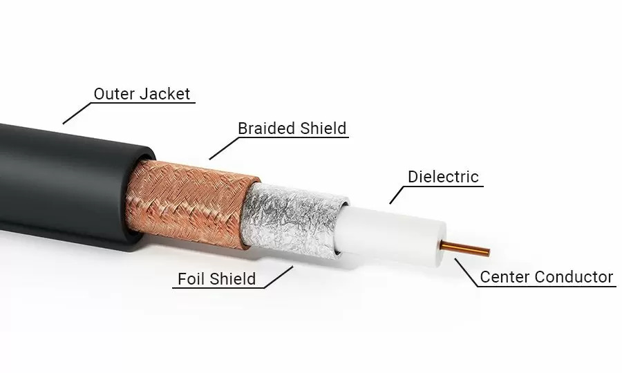
A coaxial cable is a transmission line built around a shared axis — hence “co-axial.” The construction follows a concentric four-layer design that has remained fundamentally unchanged since its invention:
- Center conductor — A solid or stranded wire (typically copper, copper-clad steel, or silver-plated copper) that carries the signal.
- Dielectric insulator — A layer of material (usually polyethylene foam or solid PTFE) that surrounds the center conductor, maintaining precise spacing and determining the cable’s impedance.
- Outer shield — One or more layers of braided wire, foil, or a combination of both. The shield serves two purposes: it contains the signal field within the cable and blocks external electromagnetic interference (EMI).
- Outer jacket — A protective sheath, typically PVC, PE, or fluoropolymer (for plenum-rated or high-temperature applications).
This layered construction is what gives coax its defining characteristic: the ability to carry high-frequency signals over distance with minimal radiation loss and excellent noise immunity. Unlike twisted-pair cables, the electromagnetic field in coax stays contained between the center conductor and shield, making it the preferred choice for RF applications from kilohertz through gigahertz frequencies.
If you’re integrating coax into a larger assembly — say, an industrial wire harness that bundles power, data, and RF lines — the cable’s physical and electrical characteristics become critical design parameters.
What Does “RG” Stand For?
RG stands for Radio Guide. The designation traces back to the U.S. military’s Joint Electronics Type Designation System (JETDS), developed during World War II to standardize electronic components across the armed forces.
The original RG specifications were published in MIL-HDBK-216, released in 1962. This handbook cataloged hundreds of RF cable types, each assigned an RG number with detailed construction and performance parameters. If you ordered “RG-58” in 1965, you knew exactly what you were getting — conductor gauge, dielectric material, shield construction, impedance, and attenuation were all locked down by the military specification.
Here’s the catch: MIL-HDBK-216 was withdrawn in 2001. It is no longer maintained, updated, or enforced. The RG designations persist purely as industry convention. A cable sold as “RG-58” today may or may not match the original MIL-HDBK-216 specification. Some manufacturers produce cables that faithfully replicate the original specs. Others cut corners — thinner shields, lower-grade dielectrics, copper-clad steel where solid copper was specified.
This is why anyone specifying coax for a critical application needs to look past the RG number and evaluate the actual datasheet. The RG label tells you the general category. The manufacturer’s spec sheet tells you what you’re actually buying.
The “/U” suffix found on many RG designations (RG-58/U, RG-213/U) stands for “Universal” or “for general utility use.” It indicates the cable meets the standard specification without special variants. Other suffixes exist — “/A” for a modified version, for instance — but “/U” is by far the most common.
The RG Numbering System: Why the Numbers Don’t Tell the Whole Story
If you’re new to RF cabling, the RG numbering system looks like it should be logical. RG-6, RG-8, RG-11, RG-58, RG-59, RG-174 — surely the numbers mean something?
They don’t. Not in any systematic way.
The original RG numbers were assigned sequentially as new cable types were registered. RG-6 is not “better” than RG-5. RG-58 is not “half” of RG-116. The numbers are essentially catalog entries, not a ranking system.
This creates several practical problems:
- No guaranteed specs. Two cables both labeled “RG-58” can have different attenuation curves, different shield coverage, and different power handling — depending on who made them and when.
- No impedance grouping. 50-ohm cables are scattered across the numbering: RG-58 (50Ω), RG-174 (50Ω), RG-213 (50Ω), RG-8 (50Ω), RG-316 (50Ω). 75-ohm cables include RG-6, RG-11, RG-59, RG-179. The number tells you nothing about impedance.
- No size grouping. RG-174 is about 2.5mm in diameter. RG-213 is about 10mm. Both are 50-ohm cables. The RG number gives no hint of physical dimensions.
The practical takeaway: treat the RG designation as a starting point, not a specification. When you’re building something that matters — a medical wire harness for diagnostic imaging equipment, for instance — you validate the cable against your actual requirements, not against a 60-year-old catalog number.
MIL-C-17: The Current Military Standard
With MIL-HDBK-216 withdrawn, the active U.S. military standard for RF coaxial cable is MIL-DTL-17 (formerly MIL-C-17). This standard defines cables using a different naming convention: “M17/” followed by a number that maps to the old RG designation.
For example:
- M17/75-RG214 corresponds to the old RG-214
- M17/28-RG058 corresponds to RG-58
- M17/113-RG316 corresponds to RG-316
The M17/ system is actively maintained. Cables qualified to MIL-DTL-17 undergo rigorous testing for attenuation, impedance stability, temperature cycling, and mechanical durability. If your application requires traceable, guaranteed performance — aerospace, defense, or critical infrastructure — specifying the M17/ designation rather than just “RG-58” is the difference between getting a cable that meets a standard and getting one that merely borrows a name.
For aerospace wire harness applications, where failure is measured in millions of dollars or worse, MIL-DTL-17 qualification is non-negotiable.
50 Ohm vs 75 Ohm: Why Impedance Matters
Coaxial cable impedance is not arbitrary. The two dominant standards — 50 ohms and 75 ohms — emerged from physics, not committee decisions.
50-ohm cables optimize for power handling. The math shows that 30 ohms gives maximum power transfer, while 77 ohms gives minimum signal loss. Fifty ohms splits the difference — a compromise that delivers good power handling with acceptable attenuation. This makes 50Ω the standard for:
- RF transmission (transmitters, antennas, amplifiers)
- Two-way radio and amateur radio
- Laboratory test equipment
- Cellular base station interconnects
- Wi-Fi antenna feeds
- Military and aerospace communications
75-ohm cables optimize for low attenuation. At 77 ohms, a coaxial cable achieves its theoretical minimum signal loss per unit length. Seventy-five ohms is close enough to this ideal while being practical to manufacture. This makes 75Ω the standard for:
- Cable television (CATV)
- Satellite TV and broadband internet
- Broadcast video (SDI)
- Home theater and AV distribution
- CCTV and video surveillance
Using the wrong impedance creates a mismatch. Connect a 50-ohm transmitter to a 75-ohm cable, and some of your signal reflects back toward the source instead of reaching the antenna. The result: higher VSWR, reduced effective radiated power, and in high-power systems, potential transmitter damage.
RG Coaxial Cable Types: Comparison Table
| RG Type | Impedance | Center Conductor | Typical OD | Common Applications | Key Notes |
|---|---|---|---|---|---|
| RG-6 | 75Ω | 18 AWG CCS | 6.9mm | CATV, satellite, broadband | Industry standard for home coax |
| RG-11 | 75Ω | 14 AWG CCS | 10.3mm | Long CATV/satellite runs, underground | Low loss, stiff, hard to bend |
| RG-59 | 75Ω | 20 AWG CCS | 6.1mm | Short video runs, CCTV, baseband video | Thinner center conductor than RG-6 |
| RG-58 | 50Ω | 20 AWG stranded | 4.95mm | Radio, test equipment, short RF jumpers | Flexible, common in labs |
| RG-8 | 50Ω | 13 AWG stranded | 10.3mm | Amateur radio, high-power RF | High power handling, thick |
| RG-174 | 50Ω | 26 AWG stranded | 2.8mm | GPS, Wi-Fi pigtails, tight spaces | Very thin, high loss at distance |
| RG-213 | 50Ω | 13 AWG stranded | 10.3mm | Broadcasting, marine, high-power RF | Rugged, similar to RG-8 but better shielding |
| RG-316 | 50Ω | 26 AWG stranded | 2.5mm | Aerospace, mil-spec, compact RF | PTFE dielectric, high-temp rated |
| RG-400 | 50Ω | 19 AWG stranded | 5.0mm | Aerospace, military, test equipment | Double-shielded, PTFE, premium |
| RG-142 | 50Ω | 18 AWG SCCS | 5.0mm | Aerospace, high-temp RF | PTFE, silver-plated conductor |
| RG-62 | 93Ω | 22 AWG solid | 6.1mm | Legacy networking (ARCnet), some video | Uncommon impedance |
| RG-179 | 75Ω | 26 AWG stranded | 2.5mm | Compact 75Ω applications, video | Thin, PTFE options available |
Cable Selection Decision Framework
Not sure which cable to use? Start here. Answer three questions and the table below gives you the answer.
Step 1: What’s your impedance?
75Ω → Go to Step 2A
50Ω → Go to Step 2B
Step 2A (75Ω): How long is the run?
Under 150 ft, indoor → RG-6
Under 150 ft, tight space / need flexibility → RG-59
Over 150 ft, or outdoor/underground → RG-11
Step 2B (50Ω): What’s your priority?
Smallest possible cable → RG-174 or RG-316 (high-temp)
Flexible, general lab/bench use → RG-58
High power (>500W) → RG-213 or RG-8
Aerospace/military, high-temp, must not fail → RG-400 or RG-142
| Your Scenario | Impedance | Distance | Environment | Recommended Cable | Budget Alternative |
|---|---|---|---|---|---|
| Home cable TV/internet | 75Ω | <150 ft | Indoor | RG-6 | — |
| Long cable drop from pole | 75Ω | >150 ft | Outdoor/UG | RG-11 | — |
| CCTV camera, short run | 75Ω | <100 ft | Indoor | RG-59 | RG-6 |
| Lab bench RF jumper | 50Ω | <10 ft | Indoor | RG-58 | — |
| GPS antenna pigtail | 50Ω | <6 ft | Indoor | RG-174 | — |
| Ham radio HF antenna feed | 50Ω | <100 ft | Outdoor | RG-213 | RG-8 |
| Mil-spec avionics | 50Ω | Any | Extreme | RG-400 | RG-142 |
| High-temp engine bay RF | 50Ω | <20 ft | High-temp | RG-316 | — |
| Broadcast transmitter feed | 50Ω | >50 ft | Outdoor | RG-213 | Hardline |
Common RG Cable Types in Detail
RG-6
The workhorse of residential and commercial video distribution. RG-6 uses an 18 AWG copper-clad steel center conductor with a foam polyethylene dielectric and typically a dual shield (foil + braid). At 750 MHz, attenuation runs roughly 5.6 dB per 100 feet. Quad-shield variants add two extra foil layers for installations in high-EMI environments — think apartment buildings with dozens of Wi-Fi networks bleeding through the walls.
RG-6 replaced RG-59 as the standard for cable TV installations because its thicker center conductor and improved dielectric deliver meaningfully lower loss at the higher frequencies modern digital cable systems use (up to 1 GHz and beyond for DOCSIS 3.1).
RG-11
When the cable run exceeds 200 feet, RG-6 starts losing too much signal. RG-11 steps in with a 14 AWG center conductor — nearly twice the cross-sectional area of RG-6’s 18 AWG — cutting attenuation roughly in half. At 750 MHz, RG-11 loses about 3.0 dB per 100 feet versus RG-6’s 5.6 dB.
The trade-off: RG-11 is thick (10.3mm OD), stiff, and has a minimum bend radius of about 100mm. You’re not fishing this through a finished wall. It’s typically used for the drop from the pole to the house, underground conduit runs, and backbone distribution in MDUs (multi-dwelling units).
RG-59
RG-59 has a 20 AWG center conductor — thinner than RG-6 — which makes it more flexible but higher-loss. At 750 MHz, attenuation is around 8.5 dB per 100 feet. It’s been largely phased out for broadband applications but still shows up in:
- Short CCTV camera runs (under 100 feet)
- Baseband video patching in broadcast facilities
- Legacy analog video systems
If someone tries to sell you RG-59 for a satellite TV installation, walk away. The higher frequencies used by modern satellite systems (950-2150 MHz on the L-band) will be attenuated to uselessness over anything but the shortest runs.
RG-58
The lab bench standard. RG-58 is a 50-ohm cable with a 20 AWG stranded center conductor, making it flexible enough to coil and uncoil repeatedly without work-hardening. At 1 GHz, attenuation is roughly 20 dB per 100 feet — fine for bench interconnects and short jumpers, unacceptable for long runs.
RG-58 is ubiquitous in test and measurement environments. BNC-to-BNC RG-58 jumpers connect signal generators, spectrum analyzers, oscilloscopes, and network analyzers in labs worldwide. It’s also common in mobile radio installations for short antenna feed lines.
RG-174
RG-174 is the go-to when space is tight. At 2.8mm OD with a 26 AWG stranded center conductor, it fits where nothing else will — GPS antenna pigtails, Wi-Fi card internal connections, SDR dongle adapters. The penalty: high attenuation. At 1 GHz, expect about 45 dB loss per 100 feet. Keep RG-174 runs under 6 feet whenever possible.
RG-213
RG-213 is the heavy lifter. With a 13 AWG stranded copper center conductor and a 10.3mm OD, it handles legal-limit amateur radio power levels (1.5 kW) without breaking a sweat. The polyethylene dielectric and double-braid shield make it rugged enough for outdoor and marine installations. Attenuation at 30 MHz is about 1.2 dB per 100 feet — excellent for HF through VHF work.
RG-316
RG-316 is essentially the high-temperature, mil-spec version of RG-174. Same 50-ohm impedance and 2.5mm OD, but with a PTFE (Teflon) dielectric rated to 200°C continuous. The stranded silver-plated copper-clad steel center conductor handles soldering without damage. Common in aerospace, military handheld radios, and any application where the cable might see engine-compartment-level heat.
RG-400
If RG-58 is the Honda Civic of coax — reliable, affordable, everywhere — RG-400 is the Porsche. Same 50-ohm impedance and similar 5mm OD, but with a PTFE dielectric, double silver-plated copper shield, and silver-plated copper-clad steel center conductor. Temperature rated to 200°C. Attenuation is slightly better than RG-58 at high frequencies. The double shield provides >90 dB of isolation. Used in aerospace, military avionics, and precision test equipment where failure is not an option.
RG vs LMR/CFD: What Modern Engineers Actually Use
The RG system is 60+ years old. Modern cable designs have leapfrogged it in performance. If you’re designing something new — not repairing legacy equipment — you should know about the alternatives.
LMR Series (Times Microwave)
LMR cables use a foam polyethylene dielectric with a bonded aluminum foil shield and tinned copper outer braid. The “bonded” part matters: the foil is literally glued to the dielectric, which prevents the shield from separating when the cable bends. This gives LMR cables significantly better shielding and lower loss than equivalent-diameter RG types.
| LMR Type | Equivalent RG | Attenuation at 1 GHz (dB/100ft) | Key Advantage |
|---|---|---|---|
| LMR-240 | RG-8X (similar size) | 10.3 | 50% less loss than RG-58 at same OD |
| LMR-400 | RG-8 / RG-213 | 3.9 | 60% less loss than RG-213, same OD |
| LMR-600 | — | 2.5 | Very low loss for long runs |
| LMR-100A | RG-174 / RG-316 | 28.0 | Better shielding than RG-174 |
When to use LMR over RG: Any new installation where cable loss matters. LMR-400 has become the de facto standard for amateur radio antenna feeds, cellular booster installations, and outdoor Wi-Fi bridge cabling. The cost premium over RG-213 is modest — roughly $0.80/ft vs $0.60/ft — and the performance difference is dramatic.
CFD Series
CFD (Cellular Foam Dielectric) cables are another modern alternative, often used in broadcast and telecommunications. They offer similar performance to LMR with different connector compatibility. If your system already uses CFD connectors, stick with CFD.
The Bottom Line
RG cables are not obsolete. They remain the right choice for:
- Repairing existing RG-based systems
- Applications where MIL-DTL-17 traceability is required (RG-400, RG-142)
- Budget-constrained projects where “good enough” is actually good enough
- Tight-bend applications where bonded-foil cables might delaminate
But for new designs with demanding RF performance requirements, LMR or CFD should be your default starting point — not an afterthought.
Key Specifications Beyond the RG Number
When you’re evaluating coax for a real project, the RG number is just the first filter. Here’s what actually matters, broken down by what you’re optimizing for:
⚡ For Signal Quality
Attenuation (Insertion Loss): Measured in dB per 100 feet. It increases with frequency — a cable that loses 5 dB/100ft at 500 MHz might lose 15 dB/100ft at 2 GHz. Always check attenuation at your actual operating frequency, not just the “nominal” spec.
Shielding Effectiveness: Single-braid shields: 40-60 dB isolation. Foil + braid (dual shield): 70-85 dB. Quad-shield: >90 dB. More shielding = less interference, but also more cost, weight, and stiffness.
🔧 For Physical Installation
Bend Radius: Typically 5-10x cable OD for static, 10-20x for dynamic (repeated flexing). Exceed it, and you kink the dielectric — creating an impedance discontinuity. A kinked cable is a damaged cable. Replace it.
Temperature Rating: Standard PVC jacket: 80°C. Plenum-rated (CMP/FT6): 150°C+. PTFE dielectric (RG-316, RG-400): 200°C continuous. For automotive wire harness applications in engine compartments, temperature rating is the difference between a cable that works for a decade and one that crumbles in six months.
📡 For RF Performance
Velocity of Propagation (Vp): How fast signals travel, as % of light speed. Solid PE: ~66%. Foam PE: ~78-84%. PTFE: ~69-70%. Critical for phased antenna arrays and timing-sensitive digital systems where cable length = signal delay.
Power Handling: Maximum power before dielectric breakdown. RG-58 handles ~500W at 10 MHz but only ~50W at 1 GHz. Power handling drops as frequency rises — always check the derating curve.
How to Identify RG Cable Types
Most quality coax cables print their specifications directly on the jacket at regular intervals. A typical marking reads:
RG-6/U 18AWG 75Ω CATV 3GHz SWEPT E123456 (UL) CM
Breaking this down:
- RG-6/U — Cable type
- 18AWG — Center conductor gauge
- 75Ω — Characteristic impedance
- CATV 3GHz SWEPT — Application and tested frequency range
- E123456 — UL file number
- (UL) CM — UL listing and fire rating (CM = communications, general purpose)
If the jacket has no markings, or the markings are vague (“RG-58 type” without any electrical specs), treat the cable as unknown quality. Physical measurements can help — OD, center conductor gauge, dielectric material — but you won’t know the electrical performance without testing.
Connector Types for RG Cables
Choosing the right connector is as important as choosing the right cable. Here’s what mates with what:
| Connector | Impedance | Common RG Types | Typical Applications |
|---|---|---|---|
| BNC | 50Ω / 75Ω | RG-58, RG-59, RG-174, RG-316 | Test equipment, CCTV, broadcast |
| F-type | 75Ω | RG-6, RG-11, RG-59 | CATV, satellite, cable modem |
| SMA | 50Ω | RG-174, RG-316, RG-58 | Wi-Fi, GPS, cellular, test equipment |
| N-type | 50Ω | RG-8, RG-213, RG-214 | High-power RF, base stations, antennas |
| TNC | 50Ω | RG-58, RG-213 | Threaded BNC variant, vibration-resistant |
| UHF (PL-259/SO-239) | Non-constant | RG-8, RG-213 | Amateur radio (legacy, poor above 300 MHz) |
Critical note: 50-ohm and 75-ohm BNC connectors look almost identical but are not interchangeable. A 75-ohm BNC has a slightly different dielectric geometry. Using a 50-ohm BNC on a 75-ohm system (or vice versa) creates an impedance bump that degrades signal integrity, especially above 1 GHz.
Installation Best Practices
Coax is forgiving compared to fiber, but it’s not indestructible. Common mistakes that cause problems:
Minimum bend radius. Every coax has one. Ignore it, and you create a permanent impedance bump. For RG-6, that’s about 35mm. For RG-11, about 100mm. When in doubt, keep bends gentle.
Cable kinking. Once a coax cable kinks, the dielectric is permanently deformed. Don’t try to straighten it — cut it off and re-terminate.
Compression vs crimp connectors. Compression connectors (the kind installed with a compression tool) provide better weather sealing and pull strength than hex crimp connectors. For outdoor installations, use compression connectors with integral O-rings.
Stripping. Use the correct stripping tool for your cable type. A three-blade coax stripper removes the jacket, shield, and dielectric in one operation with precise depth control. Utility knives and diagonal cutters are not stripping tools — they nick the center conductor and create failure points.
Weather sealing. Outdoor connections need protection. Self-amalgamating tape wrapped from the cable jacket onto the connector body, followed by a layer of electrical tape for UV protection, keeps water out for years. Skip this step, and corrosion will find its way in within months.
Grounding. NEC Article 820 requires coax entering a building to be grounded to the building’s grounding electrode system. This isn’t optional — it’s code, and it protects both equipment and people from lightning-induced surges.
Testing Coaxial Cables
After installation, test. Before troubleshooting, test. Here’s the testing hierarchy:
Continuity. A basic multimeter check verifies the center conductor isn’t broken and isn’t shorted to the shield. Quick, essential, but only catches catastrophic failures.
Impedance verification. A time-domain reflectometer (TDR) sends a pulse down the cable and analyzes reflections. It can pinpoint the exact distance to a break, short, kink, or water ingress point. Modern TDRs fit in a pocket and cost under $100.
Return loss / VSWR. A vector network analyzer (VNA) or antenna analyzer measures how much signal reflects back from the cable and its termination. High return loss (low VSWR) means the cable and connectors are doing their job. Low return loss means something is wrong — a bad connector, a kink, water in the line, or an impedance mismatch.
Insertion loss. Measure the actual attenuation through the installed cable at operating frequencies. Compare to the manufacturer’s spec. Excess loss indicates damage, poor connectors, or substandard cable.
Applications by Industry
Telecommunications and Broadcasting
RG-6 and RG-11 dominate CATV and broadband distribution. RG-213 and hardline coax handle transmitter-to-antenna feeds at broadcast towers. Cellular base stations use low-loss 50-ohm coax (typically LMR-series for new installs, RG for legacy) for jumper cables between radios and antennas.
Aerospace and Defense
RG-316, RG-400, and RG-142 are the standards here — PTFE dielectrics, silver-plated conductors, double shielding. Every gram counts, every dB of loss matters, and failure is not an option. Aerospace wire harness assemblies frequently integrate these coax types alongside power and data conductors.
Medical
MRI machines, ultrasound systems, and RF ablation equipment all rely on precision coax for signal integrity. Medical wire harness designs often specify RG-316 or RG-400 for their combination of small diameter, high-temperature tolerance, and sterilizability.
Automotive
Modern vehicles are rolling RF platforms — GPS, satellite radio, cellular, Wi-Fi, Bluetooth, radar. Automotive wire harness assemblies increasingly incorporate coax for antenna feeds and high-speed data links. Temperature rating and vibration resistance are the key differentiators from commercial coax.
Industrial
Factory automation, process control, and SCADA systems use coax for reliable data transmission in electrically noisy environments. The shield’s EMI rejection makes coax preferable to twisted pair when VFDs and motors are generating broadband interference.
Rough Price Ranges for Common RG Types
Prices vary by manufacturer, quantity, and market conditions. These are ballpark figures for bulk (500-1000 ft spools) in 2025, intended for budget estimation — not quoting.
| RG Type | Approx. Price (USD/ft) | Notes |
|---|---|---|
| RG-6 (dual shield) | $0.10 – $0.25 | Commodity pricing, quad-shield adds ~30% |
| RG-6 (quad shield) | $0.15 – $0.35 | Worth it in high-EMI environments |
| RG-11 | $0.30 – $0.60 | More copper = higher cost |
| RG-59 | $0.10 – $0.20 | Often cheaper than RG-6, but don’t use for broadband |
| RG-58 | $0.20 – $0.50 | Widely available, competitive pricing |
| RG-8 | $0.50 – $0.90 | Thick, copper-intensive |
| RG-174 | $0.15 – $0.40 | Thin but specialty = moderate cost |
| RG-213 | $0.50 – $1.00 | Premium over RG-8 for better shielding |
| RG-316 | $0.80 – $1.50 | PTFE dielectric drives cost up |
| RG-400 | $2.00 – $5.00 | Mil-spec, double-shielded, PTFE — you pay for certification |
| RG-142 | $2.50 – $6.00 | Silver-plated conductors, aerospace grade |
For comparison:
- LMR-400: ~$0.70 – $1.20/ft
- LMR-240: ~$0.40 – $0.70/ft
The price gap between RG and LMR has narrowed significantly. For new installations, the performance gain from LMR often justifies the modest premium.
Frequently Asked Questions
What does RG stand for in coaxial cable?
RG stands for “Radio Guide,” a designation from the U.S. military’s WWII-era component standardization system. The original specifications were published in MIL-HDBK-216 (1962), now withdrawn. Current military standard is MIL-DTL-17.
Source: MIL-DTL-17H, U.S. Department of Defense
What’s the difference between RG-6 and RG-11?
RG-6 has an 18 AWG center conductor and is the standard for in-home cable TV and internet wiring. RG-11 has a 14 AWG center conductor — nearly twice the cross-sectional area — giving it about half the signal loss over distance. RG-11 is used for long outdoor/underground runs where RG-6’s attenuation would be unacceptable.
Can I use 50-ohm cable for TV or internet?
No. Cable TV and broadband internet systems are designed for 75-ohm impedance. Using 50-ohm cable creates an impedance mismatch that causes signal reflections, reducing signal quality and potentially causing pixelation or dropped connections.
Source: Belden Engineering Design Guide for Coaxial Cables
What does “/U” mean in RG-58/U?
“/U” stands for “Universal” or “for general utility use.” It indicates the standard version of the cable specification without special variants.
How do I tell what type of RG cable I have?
Look for printing on the cable jacket. Quality cables print the RG type, impedance, AWG, and other specs at regular intervals. If there’s no marking, measure the outer diameter and center conductor gauge, then compare to known RG type dimensions. Times Microwave and Belden both publish dimensional reference guides.
What’s the most common RG cable for home use?
RG-6. It’s the standard for cable TV, satellite TV, and cable internet installations in residential settings. Nearly every coax outlet in a modern home connects to RG-6 somewhere in the wall.
Can I splice coaxial cable?
Yes, but every splice introduces signal loss and a potential failure point. Use F-type barrel connectors for RG-6/RG-11, or BNC barrel adapters for RG-58/RG-59. For critical applications, replace the entire cable run rather than splicing.
Source: ARRL Handbook — recommends keeping splices to an absolute minimum in antenna systems.
What’s the difference between RG-58 and RG-316?
Both are 50-ohm cables, but RG-316 uses a PTFE (Teflon) dielectric rated to 200°C, while RG-58 uses polyethylene rated to about 80°C. RG-316 is thinner (2.5mm vs 5mm OD) and typically has better shielding. RG-316 costs 4-10x more and is used in aerospace, military, and high-temperature applications.
When should I use LMR cable instead of RG?
Use LMR for any new installation where cable loss matters — antenna feeds, tower runs, outdoor Wi-Fi bridges. LMR-400 has roughly 60% less loss than RG-213 at the same diameter. Stick with RG when you need MIL-DTL-17 traceability, are repairing legacy equipment, or when budget constraints dominate.