Turn your drawing, BOM, pinout, shield path, mechanical constraints, and inspection requirements into a production-ready assembly. OUKETECH supports OEM projects from prototype and small-batch builds through high-mix and repeat volume production.
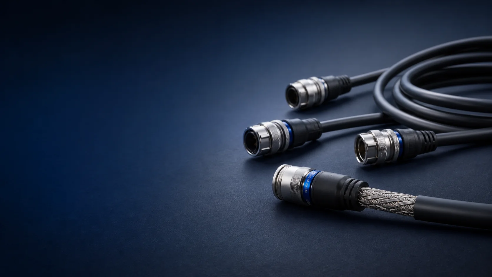
Open drawing points are returned for review before the first build, so shield termination, pinout, labels, and acceptance criteria are not left to the production floor.
A low volume shielded cable assembly manufacturer should protect revision control and material identity even when quantities are modest.
A high mix shielded cable assembly manufacturer must keep variants, work instructions, test programs, and labels separated by part number and revision.
For buyers seeking a shielded cable assembly manufacturer for volume production, the handoff begins with an approved sample and controlled build package.
Bulk cable data tells only part of the story. Shield preparation, drain-wire routing, backshell geometry, bond surfaces, connector transition, strain relief, bend space, and grounding intent all influence the finished assembly.
As a custom shielded cable assembly manufacturer, OUKETECH reviews the complete build path rather than treating shielding as a line item in the BOM. Your released drawing remains the controlling source for electrical, mechanical, and EMC requirements.
Conceptual construction view. Final materials, dimensions, ratings, and layer order follow the approved cable datasheet.
Some buyers begin with a bulk-cable search and discover that the real purchasing need is a tested, connectorized assembly. OUKETECH’s scope on this page is the finished custom assembly. The raw cable brand, part number, construction, ratings, approvals, and substitutions remain subject to project review and customer approval.
A buyer searching for a shielded cable manufacturer, shielded cable supplier, custom shielded cable manufacturer, shielded wire manufacturer, OEM shielded cable supplier, or shielded cable factory should state whether the deliverable is bulk cable or a terminated assembly. The same distinction matters when comparing a shielded cable wholesale supplier or bulk shielded cable supplier.
Requests aimed at a shielded control cable manufacturer, shielded instrumentation cable supplier, shielded signal cable manufacturer, or shielded multi conductor cable manufacturer can feed an assembly RFQ once the approved cable specification, cut length, connector interface, pinout, shield map, and test plan are defined.
A foil shielded cable manufacturer, braided shielded cable manufacturer, foil and braid shielded cable supplier, double shielded cable manufacturer, or shielded cable with drain wire supplier describes the raw-cable layer. The assembly drawing must still define how that layer is prepared, terminated, insulated, supported, and inspected.
An RS485 shielded cable supplier, shielded VFD cable manufacturer, shielded motor cable supplier, high flex shielded cable manufacturer, or drag chain shielded cable supplier may address the bulk cable. The finished assembly also needs connector transitions, bend or torsion duty, routing, grounding, strain relief, and validation requirements.
A shielded cable for industrial automation supplier or oil resistant shielded cable supplier may be one part of the approved BOM. Specify the actual oil or chemical exposure, temperature, abrasion, motion, ingress, connector, jacket, and service-life requirements instead of relying on a generic material label.
OUKETECH reviews the complete build-to-print package: approved cable, connectors, contacts, backshells, branches, labels, protection, termination method, workmanship, inspection, documentation, prototype quantity, and production demand.
The options below are reviewed against the application and approved component data. Availability, ratings, test limits, and commercial terms are confirmed per project.
A shielded twisted pair cable assembly may use an overall shield, individually shielded pairs, or a combined construction. Pair geometry, drain wires, impedance, and connector transition must remain controlled.
Foil can support coverage at high frequencies; braid can support lower-resistance circumferential paths and flexing. The cable supplier data and system validation decide the fit—not a universal rule.
For a 360 degree shield termination cable assembly, specify compatible cable, backshell, clamp or ferrule, preparation length, bond surfaces, tooling, and inspection criteria.
A custom shielded cable assembly with metal backshell needs a defined shell material, finish, cable entry, shield capture, strain relief, mating interface, and bond requirement.
An overmolded shielded cable assembly can combine shielding, connector protection, sealing intent, bend relief, and branding. Tooling, material, adhesion, and validation remain project-specific.
A custom shielded M12 cable assembly can be reviewed for pinout, coding, shell connection, cable OD, orientation, overmold or backshell, and application-specific sealing requirements.

Do not ask the operator to infer what “connect shield” means. Show preparation dimensions, shield fold-back or drain-wire route, sleeve or clamp position, shell contact area, insulation clearances, and the boundary between bonding and strain relief.
OUKETECH can perform a shielded cable assembly DFM review to identify missing dimensions, incompatible interfaces, difficult inspection points, and material assumptions before quotation. Grounding topology remains an equipment-level design decision owned by the customer.
Signal type, nearby interference, routing, motion, enclosure interfaces, temperature, fluids, and service access change the design conversation. These are project examples, not catalogue products.
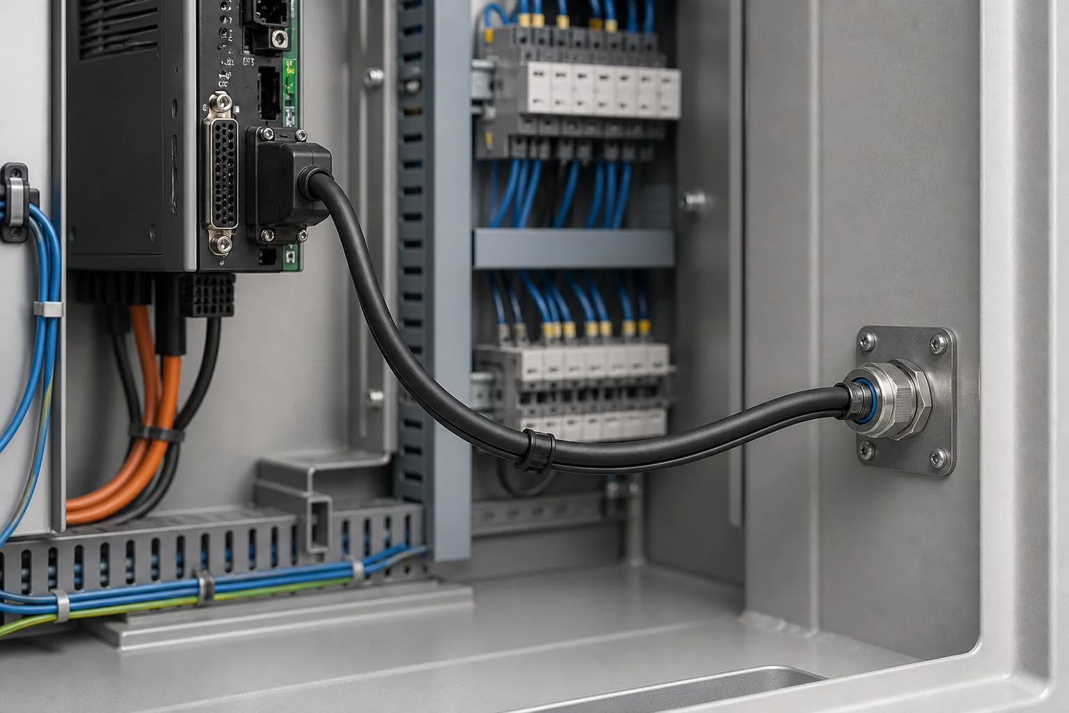
Projects may include a shielded sensor cable assembly, shielded encoder cable assembly, or shielded cable assembly for machine vision. Define signal format, connector transition, routing, flexing, and grounding in the system specification.
A shielded servo cable assembly or shielded robotics cable assembly may need separation of motor power, feedback, brake, and communication circuits plus a defined bend or torsion profile.
A shielded cable assembly for medical equipment or test and measurement equipment must follow the customer’s electrical, safety, cleaning, documentation, and regulatory requirements.
For a harsh environment shielded cable assembly, specify temperature, oil or chemicals, abrasion, vibration, ingress, UV, flexing, and installation constraints before selecting the cable and protection system.
Control cabinets, instrumentation, drives, sensors, and network interfaces can place low-level signals close to switching devices. Routing and grounding must be reviewed with the complete machine architecture.
Build-to-print programs can combine connectorized cables, branches, labels, sleeves, overmolds, and project-specific inspection records in one controlled assembly.
Review the drawing, BOM, pinout, shield and grounding map, quantities, annual demand, application, target date, and required records.
Return assumptions, missing inputs, tooling or material risks, proposed inspection scope, and project-specific commercial terms.
Build the agreed sample for fit, pinout, shield transition, workmanship, labels, and the specified checks.
Freeze the accepted revision, approved materials, work instructions, inspection points, test program, and packaging.
Support low-volume, high-mix, and repeat volume requirements against the same controlled product definition.
Route substitutions, revisions, deviations, or process changes through the agreed approval path before use.
A shielded cable assembly manufacturer with continuity testing can verify programmed connections and shorts, but continuity alone does not prove shielding effectiveness. Each project should name the method, limit, fixture, sample plan, and required record.
OUKETECH’s website identifies in-house continuity, insulation, and functional testing. Product-specific equipment, limits, sampling, record format, and any specialized EMC testing are confirmed during quotation.
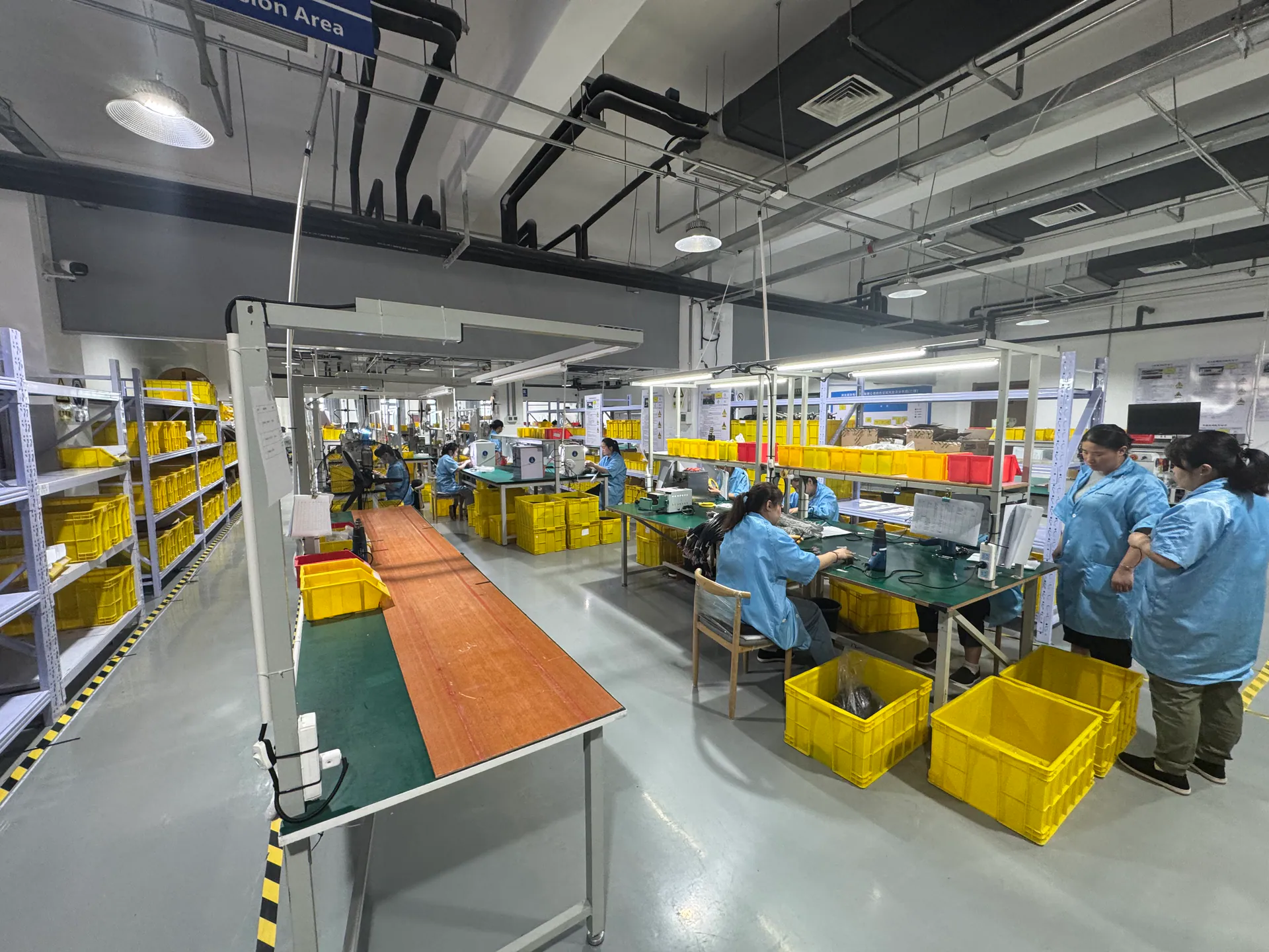
Can the supplier work from the released drawing, BOM, pinout, cable datasheet, connector instructions, and shield map? How are open points and substitutions approved?
How are cable preparation, shield termination, crimping, soldering, overmolding, labels, revision control, and work instructions managed?
Which inspections and tests apply, what are the limits and sampling rules, and what first article or traceability records will be delivered?
For broader supplier and factory context, review OUKETECH’s custom cable assembly services, industrial wire harness manufacturing, robotics cable assemblies, overmolded cable assemblies, and factory and quality-system overview.
A useful shielded cable assembly quotation depends on design complexity, materials, tooling, inspection, documentation, quantity, and supply conditions. These same shielded cable assembly cost factors determine the project-specific MOQ and lead time.
Released dimensions, tolerances, pinout, shield map, labels, branches, backshell details, and workmanship requirements.
Cable and connector part numbers, contacts, shells, backshells, sleeves, overmold materials, and approved alternatives.
Signal or data use, interference sources, grounding concept, routing, bend or torsion duty, temperature, fluids, vibration, and ingress.
Continuity, insulation resistance, hipot, shield bond, mechanical, environmental, EMC, first article, and traceability requirements as applicable.
Prototype quantity, order quantity, annual forecast, target sample date, production schedule, shipping destination, and packaging needs.
Identify assumptions that need engineering confirmation instead of embedding them in a purchase order or leaving them to production.
Yes. OUKETECH can review drawings, BOMs, pinouts, cable and connector data, shield maps, samples, and acceptance requirements for a build-to-print project. Missing design inputs are returned for confirmation before release.
OUKETECH’s current site presents support from prototypes and low-volume production through mass production. The applicable MOQ, tooling, sample timing, production lead time, and capacity are confirmed for the approved project and material supply conditions.
The team can review manufacturability and component compatibility, but the final selection must follow the equipment’s interference environment, frequency range, routing, motion profile, connector transition, grounding concept, and validation plan.
Compatible cable, connector, backshell, clamp or ferrule, preparation, tooling, strain relief, inspection, and bond requirements must be reviewed together. Availability and capability are project-specific.
The website identifies continuity, insulation, and functional testing. Pinout, shorts, insulation resistance, hipot, shield-to-shell resistance, transfer impedance, EMC, pull, flex, or environmental checks apply only when the method, limits, fixture, sampling, records, and commercial scope are agreed.
Raw cable and connector availability, shield construction, termination method, backshell or overmold tooling, dimensional complexity, inspection, test evidence, documentation, quantity, forecast, and shipping requirements all affect quotation and schedule.
Define the drawing revision, BOM, dimensional report, pinout and electrical results, workmanship evidence, material or compliance documents, deviations, packaging, and approval authority required for the project.
Use the form to share your drawing, BOM, cable and connector part numbers, shield path, quantities, application, target dates, and required inspection records. OUKETECH will review what is needed for a project-specific quotation.