Custom cable assembly · Build to your specification
Need a compact cable assembly terminated with JST connectors? OUKETECH builds customer-specified cable assemblies from approved drawings, BOMs, samples, and test requirements. Share the exact connector series and part numbers so mating, wire, length, and inspection details can be reviewed before quotation.
○Build-to-print RFQ review
○Prototype and production planning
○Project-defined inspection
Scope of supply
“Micro JST” is commonly used as a broad search term, but JST is a manufacturer with multiple connector series. A cable that looks similar or shares a pitch may still use a different housing, contact, latch, or mating interface.
This page covers custom cable assemblies built with the connector components specified for an OEM project. OUKETECH reviews the released drawing, BOM, sample, pinout, and acceptance requirements before quoting. Connector selection and system design remain governed by the equipment maker’s approved specification.
For broader manufacturing scope, see OUKETECH custom cable assembly manufacturing.
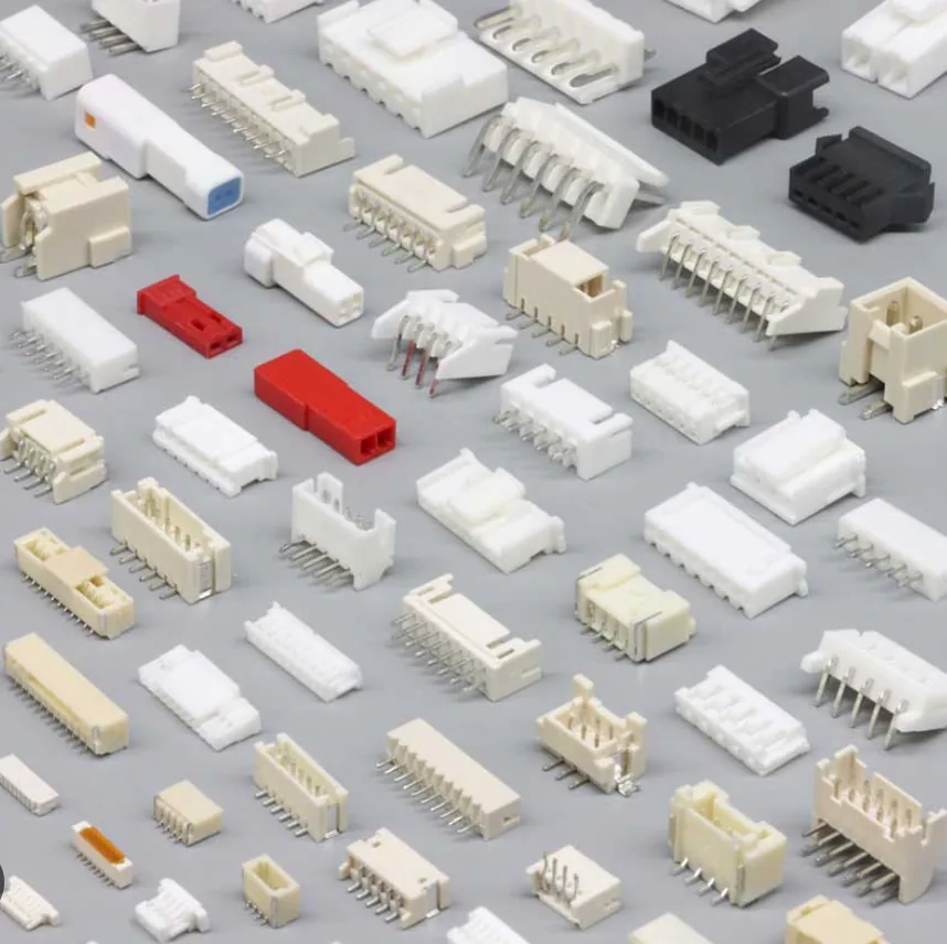
Cable assembly work at an OUKETECH production station.
Build-to-print options
The connector is one item in the build package. The wire, pinout, finished dimensions, routing, protection, and acceptance criteria determine whether the delivered assembly fits the intended equipment.
Specify the JST series, housing and contact part numbers, circuit count, mating side, orientation, keying, and any approved alternate. Identify the board header or mating connector where applicable.
Define conductor size, insulation type, colors, cable length and tolerance, branch dimensions, strip length, labels, and routing constraints. Include a drawing or marked-up sample when dimensions are critical.
List sleeving, heat-shrink, strain relief, bundling, identification, individual packaging, and handling requirements. Confirm each option against the application and approved build documents.
Series and compatibility
Pitch is useful for identifying a connector family, but it does not confirm that two parts mate. The exact series, housing, terminal, header, contact arrangement, wire range, and orientation all matter. Electrical load, temperature, vibration, and enclosure conditions also affect suitability.
For compact wire-to-board examples, review the official JST SH series profile and official JST PH connector profile. These are specific series references, not a universal definition of “micro JST”; confirm the current datasheet and exact part numbers for your project.
For a practical XH-versus-PH comparison, see OUKETECH’s JST-XH and JST-PH connector selection guide.
Typical project contexts
JST connector families appear in a wide range of electronic products. The examples below describe possible project contexts, not a blanket suitability claim for every series or assembly.
Internal signal or power connections defined by the board and system design.
Compact equipment interconnects where pinout, routing, and retention are documented.
Customer-specified cable assemblies for internal connections and service interfaces.
Project-specific leads subject to verified connector, conductor, current, and temperature limits.
From RFQ to repeat orders
The approved drawing and inspection plan should stay connected throughout quoting, sample review, and production release.
Review drawing revision, BOM, connector part numbers, pinout, dimensions, quantity, application, and required records.
Confirm material availability, open questions, process assumptions, inspection scope, commercial terms, and any tooling requirement.
Evaluate the agreed sample for fit, mating, pinout, length, workmanship, labeling, and specified tests before production release.
Build to the approved revision, inspection criteria, packaging instructions, and change-control requirements.
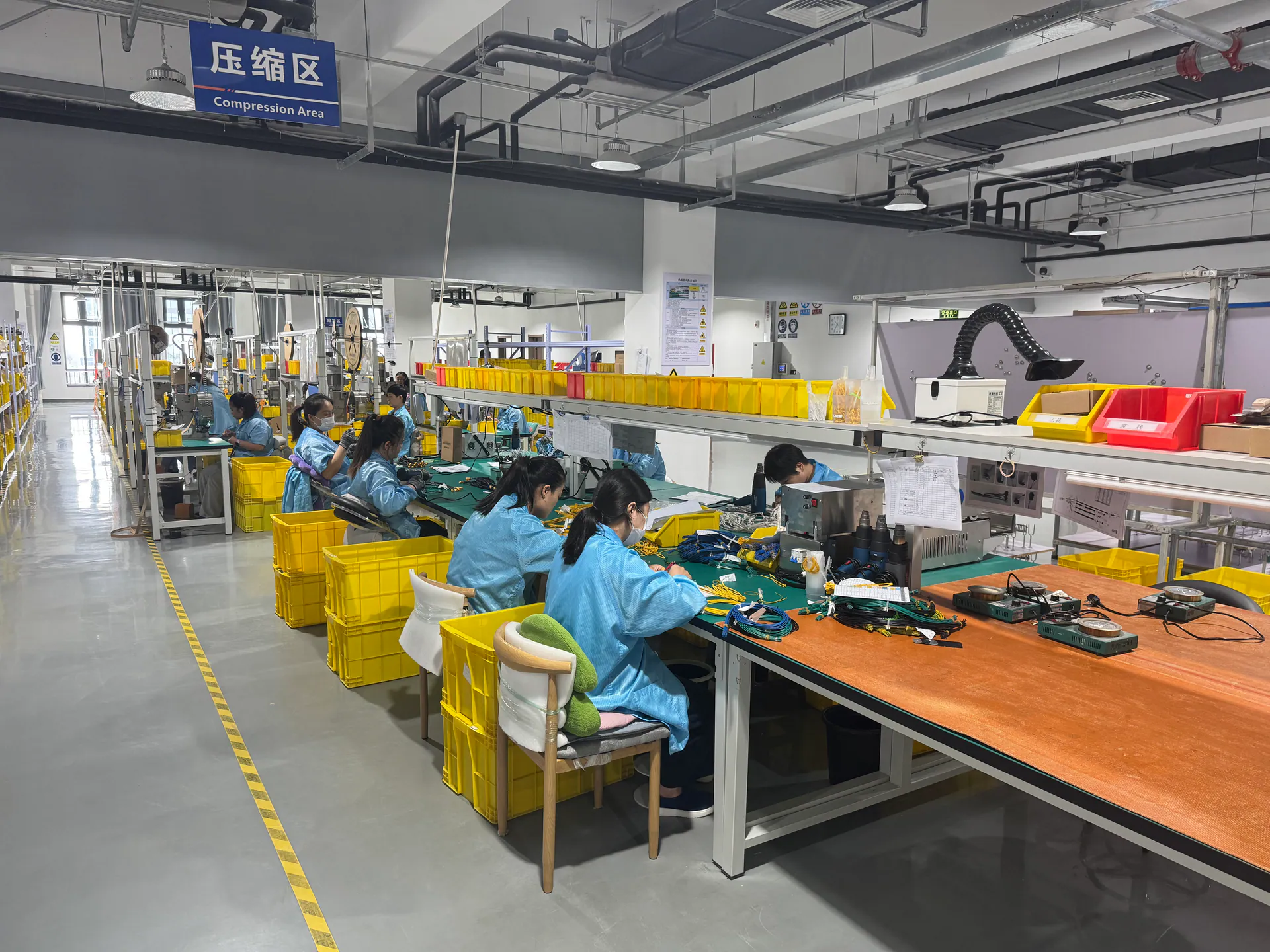
OUKETECH cable assembly production workstations.
Inspection and test plan
Inspection should follow the released drawing and project acceptance plan. Depending on the assembly and agreed scope, checks may include visual workmanship, finished dimensions, connector orientation, wire identification, pinout, continuity, open circuits, shorts, and polarity.
Continuity testing confirms an electrical path under the defined test setup; it does not by itself establish current capacity, environmental suitability, connector retention, or equipment-level reliability. Additional electrical or mechanical tests need an agreed method, limit, sample plan, and record format.
| Review item | Define in the project documents |
|---|---|
| Connector interface | Exact series and component part numbers; mating side and orientation |
| Electrical verification | Pinout, open/short coverage, polarity, test limits and record format |
| Dimensions | Overall length, branch length, tolerances, datums, and label location |
| Workmanship | Visual acceptance criteria and any required workmanship standard/class |
| Traceability | Lot identification, inspection records, and retention requirements |
RFQ checklist
A complete RFQ helps suppliers quote the same configuration and makes assumptions visible before samples are built.
Commercial planning
Commercial terms for a custom JST cable assembly depend on the exact connector and wire selection, component availability, assembly steps, tooling or fixtures, quantity, inspection scope, packaging, and shipping requirements.
There is no single MOQ or lead time that applies to every part number and order profile. Include your prototype quantity, annual demand, and target dates so the quotation can identify assumptions and confirm current supply conditions.
Part-number specificity, sourcing route, availability, and approved substitutions.
Wire preparation, assembly complexity, dimensions, labels, protection, and any tooling.
Prototype and order volumes, inspection depth, testing, reports, and packaging.
Related OUKETECH resources
See the broader build-to-print workflow for OEM cable assembly programs.
Compare a related connector-family page and its project specification approach.
Send your drawing, BOM, sample details, and sourcing requirements for review.
Buyer questions
It is a custom cable assembly using the exact JST connector family and component part numbers identified in the customer’s drawing or BOM. “Micro JST” alone is not enough to determine a compatible connector.
No. Pitch is one identification attribute. Confirm the series, housing, terminal, mating header, orientation, circuit count, wire range, and approved part numbers against the manufacturer information and project documents.
Submit the required connector part numbers, cable or wire details, pinout, length, dimensions, quantity, and acceptance criteria. Feasibility and commercial terms are confirmed for the specific build package.
Send the released drawing and revision, BOM, mating interface, pinout, wire specification, finished dimensions, sample and production quantities, target dates, inspection requirements, and packaging or documentation needs.
Availability depends on the exact part number, sourcing route, and current supply conditions. The quotation should identify the proposed component source and any substitution assumptions for customer approval.
Inspection and electrical tests must be defined in the project plan. Depending on the agreed requirements, this may include visual, dimensional, pinout, continuity, open/short, or polarity checks. Ask for any additional test and reporting scope in the RFQ.
MOQ and timing depend on materials, tooling, order quantity, validation, inspection scope, and current supply conditions. Provide your prototype quantity, annual volume, and requested dates for a project-specific quotation.
Request a quotation
Send the connector details, drawing, BOM, pinout, quantities, and target dates. The team can review the configuration and identify missing information for a project-specific quote.
Share it with your drawing and BOM to begin a build-to-print cable assembly review.