A cable that bends during installation is not automatically suited to repeated movement. OUKETECH helps OEM teams specify custom high-flex cable assemblies around the actual path, speed, bend radius, torsion, electrical load and operating environment.
Send your drawing, cable specification or sample for a build-to-print review. We can review conductor and jacket requirements, shielding, connectors, length, routing and the inspection plan for your project.
Factory-direct manufacturing · Build-to-print customization · Project-defined inspection
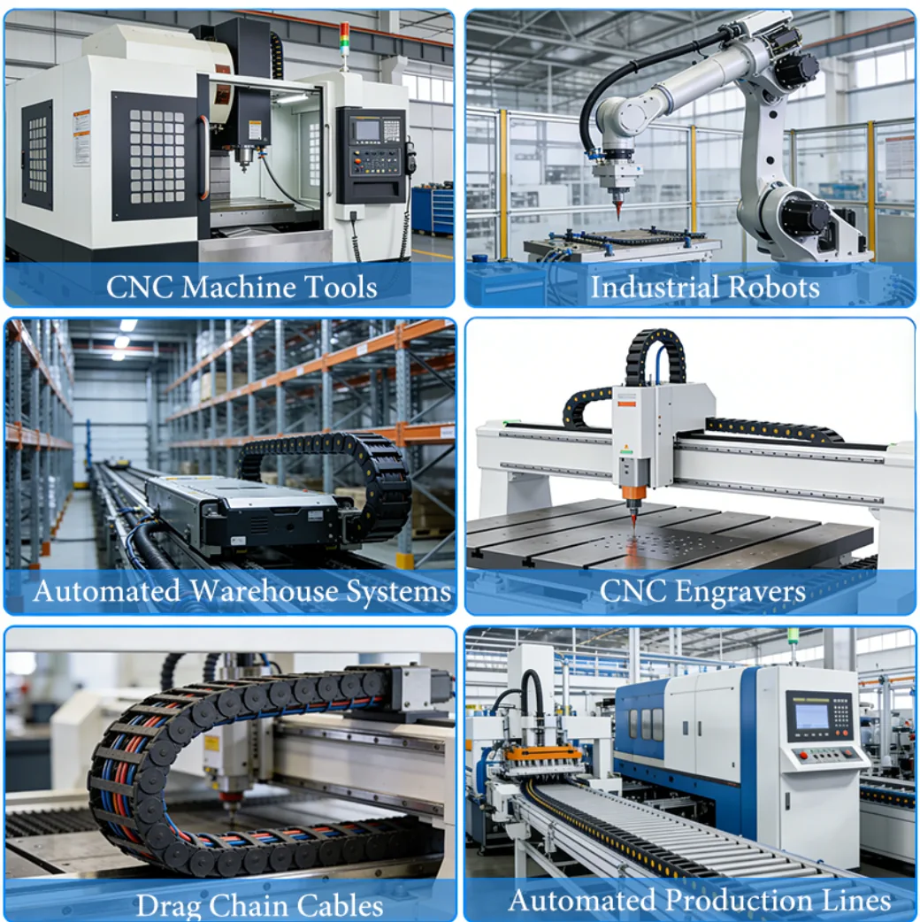
“High flex” and “ultra flexible” are useful product terms, but they do not define one universal cable construction or cycle-life rating. A cable that works in a slow, wide-radius moving track may not suit a compact robot joint that bends and twists at the same time.
The design has to match the movement the cable will see. If the motion profile is incomplete, a general product label can hide tighter bends, faster travel or more torsion than the design can tolerate. Define the movement and acceptance criteria before treating a cable as suitable for continuous flex.
Selection principle: Specify the motion and the acceptance test. Do not use “high flex” as a substitute for either.
The same cable can see very different mechanical loads depending on where it moves and how the equipment cycles.
| How the cable moves | What to define | Why it changes the design |
|---|---|---|
| Fixed after installation | Static bend radius, routing and service access | The cable may only need to tolerate installation bends, not repeated cycling. |
| Occasional repositioning | Bend location, frequency and handling method | Intermittent movement differs from a cable that moves every machine cycle. |
| Drag chain or linear axis | Travel, speed, acceleration, bend radius and cycle definition | Track guidance does not remove the effects of fill, restraint, routing and motion. |
| Robotic arm or moving joint | Bend plus torsion, joint path, moving length, speed and acceleration | Multi-axis movement can combine twisting and bending along the cable. |
| Repeated flex in a confined space | Minimum installed radius, support and neighboring components | Tight routing can concentrate strain even if a cable is marketed as flexible. |
If the cable twists, travels in a chain or moves through multiple axes, share a layout or video when possible. A motion sketch is more useful than the word “continuous.”
High-flex cable assemblies may be considered for moving equipment, including drag-chain axes, robotics, automated machinery, pick-and-place systems, mobile equipment and moving sensor or control connections. Suitability depends on the exact cable construction, assembly geometry and duty cycle; an application label alone does not establish service life.
Define stroke, speed, acceleration, bend radius, chain fill, cable separation and the full travel path.
Review cable path and connector transition through the full range of motion, including combined bending and torsion. See robotics cable assembly support.
Confirm routing, abrasion points, moving length, service access and environmental exposure before selecting a construction.
A high-flex assembly is a system of conductors, insulation, jacket, shielding, termination and routing. OUKETECH reviews customer-defined requirements for the complete assembly.
Conductor count, wire size, stranding, voltage/current, and separation of power, signal or data circuits.
Material, outside diameter, temperature range, abrasion or fluid exposure, and applicable material requirements. Confirm exact grades and availability by project.
Noise environment, shield coverage and termination, grounding points, and connector transition. Explore custom shielded cable assemblies.
Finished length and tolerance, branch points, bend radius, travel envelope, torsion, support and clearance.
Manufacturer part numbers, pinout, orientation, contact termination, backshell and strain-relief requirements.
Braid, conduit, sleeving, labels, boots or overmolding where the design calls for them. See overmolded cable assemblies.
Design tradeoff: A thicker jacket, additional shielding or added protection can affect outside diameter, stiffness, bend radius and routing space. Confirm that the complete assembly—not only the cable datasheet—fits the motion envelope.
“Ultra flexible” may describe how easily a cable bends by hand or during installation. Manufacturers may use these terms differently, so the adjective alone does not establish continuous-motion suitability.
Compare construction, minimum dynamic bend radius, motion type, speed or frequency, travel, torsion, temperature, test duration or cycles, sample configuration and pass/fail criteria.
A test result applies to the tested setup. Do not treat it as a guarantee for a different installation without engineering review.
Share the cable route, motion axes, electrical requirements, environment and installation space.
Confirm bend radius, travel, speed, acceleration, torsion, temperature, support and acceptance criteria.
Check drawing revision, BOM, connectors, pinout, length datum, branch dimensions, labels and approved materials. See the custom cable assembly process.
Confirm fit, routing, connector orientation and installation clearance before production release.
Select electrical, dimensional, visual, functional or motion tests that match project acceptance requirements.
Maintain the approved revision, BOM, work instructions and change-approval path for repeat builds.
Sample approval confirms the agreed sample criteria. It does not establish a cycle-life claim unless a defined motion test is completed.
A continuity check can confirm intended electrical paths; it does not establish flex life. A cable flex test is meaningful only when the sample configuration and motion conditions are documented.
For a project-specific validation plan, define the cable and assembly revision, sample configuration, bend radius and direction, torsion, travel, speed, acceleration, cycle definition, test duration, temperature, failure criteria, sample count and report format.
Scope matters: Company-level quality certifications do not certify a particular cable. Confirm current certificate scope and the tests available for this product program before publication or order release.
| Check | What it can establish | What still needs definition |
|---|---|---|
| Continuity / shorts | Intended paths and unintended connections | Test coverage, limits and record format |
| Dimensional / visual | Specified build dimensions and visible workmanship | Drawing revision, tolerances and acceptance criteria |
| Flex / torsion | Performance under a documented motion setup | Radius, motion, temperature, cycles and failure criteria |
| Environmental / functional | Only the specific condition and function tested | Method, sample plan, limits and report requirements |
A useful RFQ includes as many of these items as are available. If the cycle profile or bend radius is not known yet, identify it as an open design input.
OUKETECH can identify missing inputs for review. The design authority should approve final operating limits, material selections and acceptance criteria. For broader build-to-print support, see custom cable assembly manufacturing.
Not necessarily. “High-flex” is often a broad product description. “Continuous-flex” usually signals repeated movement, but still needs a defined motion profile and supporting test conditions before it can be used as an acceptance requirement.
No. Easy hand-bending does not demonstrate drag-chain life. Chain travel, speed, acceleration, bend radius, cable support, fill and temperature all affect performance. Compare the construction and test setup against your installation.
Use the cable manufacturer’s guidance for the exact construction and confirm whether the value is for static installation or repeated motion. Assembly routing, connectors, supports and operating conditions can affect required clearance.
Some cable constructions are designed for combined movement, but suitability depends on the direction, angle, rate and frequency of both motions. Describe the actual path and torsion profile, then validate the complete assembly under representative conditions.
OUKETECH’s custom cable assembly service supports build-to-print projects using customer drawings, BOMs, pinouts, samples and project requirements. Confirm the specific construction, tests, materials and commercial terms during quote review.
Start with the failure modes and acceptance criteria. Continuity may verify circuit paths; dimensional or visual inspection may confirm build details. If repeated motion is critical, define a representative flex or torsion test, setup, conditions, cycle definition and pass/fail limits.
Send clear photos, measurements, connector part numbers and application details. Identify what must remain unchanged and what may be revised. Review and approve reverse-engineered dimensions and assumptions before production.
Send OUKETECH your drawing or sample, motion profile, connector details, target quantity and validation needs to start a project review.