Drawing-defined display connections
Specify the VGA connection around your equipment: cable length, HD15 connector orientation, mounting hardware, shielding, and pin assignment. OukeTech reviews drawings, samples, and interface requirements for custom assemblies used in industrial displays, embedded systems, and equipment upgrades.
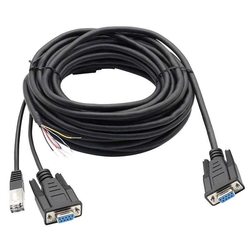
A display port behind a recessed panel leaves little room for a standard connector hood. Inside a compact machine, excess cable can obstruct service access, while an unsuitable exit direction can force a tight bend immediately behind the connector.
Custom VGA cables address these installation details alongside the electrical connection. The specification can define connector gender at each end, backshell dimensions, cable exit direction, overall diameter, mounting hardware, and finished length.
Electrical requirements deserve the same attention. RGB video paths, synchronization signals, display identification connections, and shield termination must follow the source and display interfaces. Two assemblies with matching connector shells can have different internal wiring.
For equipment with specific grounding or interference requirements, review the shield termination and backshell options as part of the complete connection.
Specify the video cable construction and impedance requirements rather than describing the assembly only as “15-pin VGA.” The RGB paths, terminations, and transitions should be evaluated together against the intended display mode.
Record the available installation envelope, connector orientation, hood dimensions, and cable exit direction. For angled connectors, include a drawing showing the mating face and installed position; “left-angle” alone can be ambiguous.
Identify which DDC connections and associated conductors the equipment needs. Document intentionally omitted pins so a production cable does not silently inherit the wiring of an incomplete reference sample.
Show how the shield connects to the connector shell or designated termination point. Include preparation dimensions and mechanical retention requirements where applicable. Shield bonding and cable strain relief need separate definitions.
Continuity checks identify wiring connections; they do not establish image quality at a specified resolution and length. Define electrical inspection separately from any required source-to-display functional validation.
VGA 使用模拟 RGB 视频信号,标称视频路径阻抗为 75 欧姆,这与线缆的选择密切相关。DDC 提供独立的通信路径用于读取显示信息。这些功能需要比连接器引脚数量更详细的信息
| Specification item | Information to include |
|---|---|
| Connector interface | HD15/DE-15 connector part numbers, male or female at each end, mating references |
| Mechanical arrangement | Straight or angled exit, hood envelope, panel recess, screw or jackscrew details |
| Finished dimensions | Length measurement reference, tolerance, cable diameter, breakout dimensions if applicable |
| Video construction | RGB coaxial construction, nominal impedance requirement, approved cable specification |
| Wiring definition | RGB, synchronization, grounds, DDC connections, pin 9 requirement, unused pins |
| Shielding | Individual and overall shields where specified, shell connection, termination method |
| Operating conditions | Temperature, abrasion, vibration, movement, and any cleaning or fluid exposure |
| Display validation | Source model, display model, resolution, refresh rate, installed cable length, acceptance criteria |
Maximum usable length and display mode must be established for the selected construction and connected equipment. Neither a connector style nor a continuity result provides a universal resolution guarantee.
OukeTech’s custom assembly development scope includes drawing and sample review, connector configuration, shielding, labels, and overmold customization. For a VGA project, the component combination and manufacturing method need confirmation against the actual installation.
Provide:
Where a molded hood or unusual exit geometry is requested, include the enclosure constraints early. Tooling, cable bend space, assembly access, and inspectability can affect whether the proposed shape is practical.
A custom assignment can be reviewed, but connector shape does not make the wiring interchangeable with standard VGA equipment. Identify the nonstandard configuration on the drawing and assembly label to reduce incorrect connections during installation or servicing.
Start with the intended acceptance decision. Pin mapping and short-circuit checks address wiring correctness. If display performance matters, specify the source, monitor, operating mode, cable length, and functional test criteria. Additional electrical measurements require an agreed method and scope.
Include the assembly part number, revision, variant identifier, and label location in the specification for review. Keep the identification visible after installation where practical, particularly when externally identical connectors carry different assignments.
List the destination market and required documentation in the RFQ. Material declarations, component evidence, inspection records, and shipment identification serve different purposes. Confirm availability for the approved BOM; a material declaration alone does not establish compliance of the finished equipment.
OukeTech’s published cable assembly service combines drawing review, component sourcing, manufacturing, and project-specific inspection. Its DFM process addresses issues such as incomplete pinouts, difficult bend locations, ambiguous shield connections, and tolerances that cannot be inspected consistently. Review the engineering and manufacturing approach.
Share the connector views, pinout, required length, enclosure clearance, and target display mode. If you are replacing an existing cable, include photographs of both ends and identify any known installation or image-quality problems.