

Custom wire harness design turns electrical requirements into a repeatable assembly that fits the equipment, survives its operating environment, and can be inspected against clear acceptance criteria. For OEM engineers and procurement teams, the most useful starting point is a coordinated drawing, bill of materials, connection table, routing plan, and test specification.
A harness can match a schematic and still create installation delays, maintenance problems, or expensive production changes. These ten practical tips for designing custom wire harness assemblies focus on the decisions that connect engineering intent with supplier execution. Use them when preparing a new design, reviewing a prototype, or requesting a manufacturing quotation.
The branched assembly below illustrates the relationship between the main trunk, breakout points, connectors, and identification sleeves.
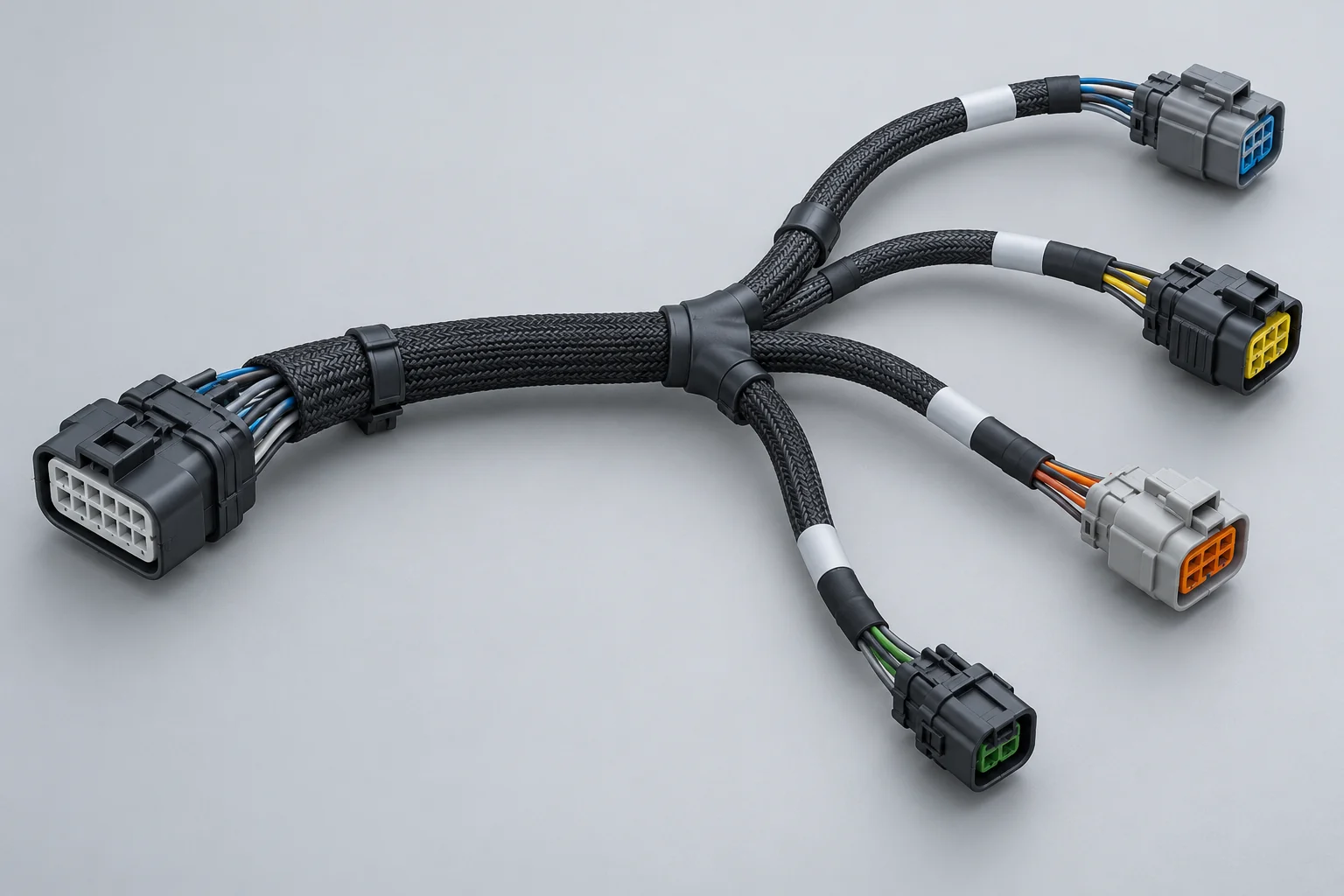
AI-generated concept illustration of a branched harness; not an OUKETECH product photograph or a production drawing.
1. Start Custom Wire Harness Design with an Application Requirements Sheet
Define what the harness must do before selecting individual parts. Record the circuits, operating loads, installation space, environmental exposure, service access, and expected production quantities. A shared requirements sheet helps the OEM and supplier quote the same scope and identify decisions that need engineering approval before prototype work begins.
Separate continuous loads from intermittent loads, and identify startup or inrush conditions. Describe nearby heat sources, vibration, cleaning chemicals, moisture, and moving mechanisms. An internal control cabinet and an outdoor machine can require different materials even when their connection diagrams look similar.
For a custom wire harness for industrial equipment, define the actual equipment zones rather than describing everything as industrial grade. Identify which branches remain protected inside the enclosure and which reach sensors, motors, or external interfaces. OUKETECH's industrial wire harness manufacturing page provides a relevant starting point for discussing that application.
Assign an owner to every unresolved item. An assumption about connector orientation or washdown exposure should become a documented question, not an invisible purchasing decision. Distinguish mandatory operating requirements from preferences that can change during design review.
2. Select Wire Size from the Complete Electrical and Thermal Conditions
Choose conductor size using the electrical load, permitted voltage drop, ambient temperature, bundling, termination limits, and applicable equipment requirements. Wire gauge alone does not establish a safe current rating for a finished harness. Confirm the actual wire construction and connector combination before releasing a bill of materials for purchasing.
Include the full current path when evaluating voltage drop, including the return path and relevant connection resistance. A conductor that meets temperature requirements may still create unacceptable voltage loss at the load. Shared return conductors also need evaluation against the currents they actually carry.
Check that the selected terminal accepts the conductor cross-section, strand construction, and insulation diameter. Two wires with the same nominal gauge can have different outside diameters and termination behavior. Increasing conductor size can affect seal fit, connector cavity compatibility, bundle diameter, and assembly labor.
Avoid specifying a universal temperature rating for PVC, silicone, or another insulation family. Use the selected wire's datasheet and assess its suitability for the application. Procurement should retain the approved wire specification so an apparently equivalent substitution does not silently change the design.
3. Specify Connectors, Terminals, Seals, and Mating Parts as a System
Treat the connector interface as a complete system. Define the housing, terminals, mating connector, seals, cavity plugs, secondary locks, and required tooling. Confirm electrical ratings and mechanical compatibility for the exact configuration. A matching pin count or a similar housing shape is insufficient evidence that two connector systems are interchangeable.
For OEM wiring harness connector selection, consider polarization, retention, service access, mating cycles, and protection against incorrect connection. Where adjacent connectors look similar, use deliberate keying or other error prevention supported by the equipment design. Color can assist identification, but it should not carry the entire error-prevention strategy.
Record manufacturer part numbers and approved alternatives separately in the bill of materials. Require engineering approval before changing a terminal plating, seal, or housing family. An alternative may require different tooling, revised drawings, new fixtures, and repeat validation even when its piece price is lower.
Ask the supplier to confirm access to the required application tooling. Molex's application tooling resources explain how to locate tooling specifications using the tool or applicator part number. Use the documents for the actual selected components rather than a generic crimping guide.
4. Define Branch Dimensions, Routing Datums, and Service Access
Dimension the harness from clearly identified reference points, and explain how each length is measured. Specify connector orientation, breakout locations, protective covering lengths, and relevant tolerances. Check the design in the equipment because a flat harness layout cannot fully represent installation obstacles, connector access, or movement during servicing.
For a wire harness drawing with branch dimensions, distinguish cut wire length from finished assembly dimensions. State whether a dimension follows the routed centerline, uses a straight reference, or terminates at a connector datum. Ambiguous measurement conventions can make two otherwise competent suppliers deliver different assemblies.
Provide service slack where needed without creating loose loops near moving parts. Check latch access and the space required to mate or remove connectors. Choose bend radii from the cable manufacturer's guidance and actual installation conditions; repeated movement requires more scrutiny than a one-time installation bend.
The routing concept below shows the relationship between gentle bends, supported branches, and enclosure clearance. Exact clearances and bend limits belong in the released design.
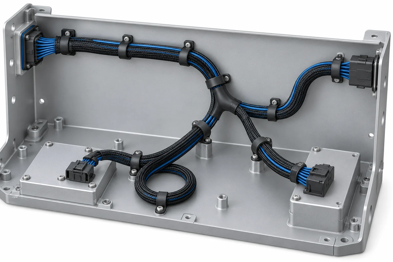
AI-generated routing concept; dimensions, support spacing, and bend limits require project-specific engineering review.
5. Match Protection to Abrasion, Moisture, Heat, and Motion
Choose sleeving, conduit, tape, grommets, and strain relief for the hazards present along each branch. Protection should address a defined exposure while preserving installation access and serviceability. Covering the whole harness with a heavier material can increase diameter and labor without resolving vulnerable connector exits or enclosure penetrations.
Evaluate edges, clips, fasteners, and moving interfaces for abrasion and pinch risk. Position supports so loads do not concentrate at terminals. Where a branch exits an enclosure, consider the entry hardware and environmental interface together with the cable itself.
A sealed connector does not make the complete harness waterproof. Seals, unused cavities, cable entries, joints, and mating conditions can each affect moisture protection. Document the required exposure and verification method rather than relying on a general waterproof label.
For applications that need encapsulated exits or integrated strain relief, review the feasibility of overmolded cable assemblies. Tooling expense, material compatibility, repairability, and the difficulty of later design changes should be evaluated before choosing overmolding.
6. Plan Signal Routing and Shield Termination Early
Identify sensitive signals and interference sources before the harness layout is fixed. Decide which circuits require separation, twisting, shielding, or controlled cable construction based on their interfaces and operating environment. Define shield terminations and grounding connections in the drawing so the assembler does not have to interpret an incomplete electrical intent.
Routing motor power beside a low-level sensor circuit can create a different interference problem from routing two ordinary power branches together. The required mitigation depends on the signal, switching behavior, cable length, enclosure, and grounding arrangement. A shielded cable should not be treated as a universal cure for an unresolved system layout.
For a shielded wire harness assembly, document how the shield connects at each interface and how that connection is physically made. Avoid prescribing one-end or both-end grounding as a universal rule. Validate the chosen arrangement against the system's electromagnetic compatibility requirements.
For communication interfaces, retain the cable construction and termination features required by the interface specification. Continuity alone cannot demonstrate signal integrity. Include any required performance testing in the purchasing scope rather than assuming a standard electrical harness test covers it.
7. Design Terminations for Repeatable Manufacturing
Review termination details with the supplier before approving prototypes. Confirm stripping requirements, compatible wire and terminal combinations, crimp tooling, inspection methods, and access for assembly. Good design for manufacturability makes the approved connection repeatable and inspectable; it also reduces dependence on undocumented operator judgment during production.
Do not transfer crimp height or pull-force criteria from an unrelated terminal family. These values depend on the selected components and applicable specifications. TE Connectivity's QP 6.5 application specification illustrates the use of component-specific termination requirements; it is not a specification for every harness.
Include splice construction, location, protection, and branch effects in the drawing. A splice placed at a breakout or tight bend can complicate routing and inspection. Ask whether the design leaves enough working length for the intended assembly sequence and tooling.
Review crimp quality using complementary checks. Visual inspection, dimensional checks, and destructive sample testing answer different questions. A pull test by itself does not establish every aspect of electrical performance or termination quality, and destructive testing requires an agreed sampling plan.
8. Define Acceptance Criteria and the Electrical Test Scope
Specify what acceptance means before the supplier builds the test fixture. Define the connection map, prohibited connections, inspection requirements, test methods, limits, and record requirements. Distinguish checks performed on every assembly from qualification or destructive tests performed on samples, and agree how changes will trigger repeat verification.
A custom wire harness continuity test should follow the approved netlist and also address unintended connections through a defined shorts check. These checks do not establish environmental durability, current capacity, or signal quality. Additional tests must follow the design risks and the equipment's requirements.
If insulation resistance or dielectric withstand testing is required, define the procedure, limits, and treatment of connected electronics. Applying an arbitrary high voltage to an assembly containing sensitive components can damage it. The responsible engineering team should approve the method and any exclusions.
When invoking IPC/WHMA-A-620, identify the contractually applicable revision and acceptance class. It addresses cable and harness assembly requirements and acceptance; it does not replace application design validation. IPC's public introduction to wire harness training identifies design, terminations, shielding, and related standards as distinct subjects requiring coordinated knowledge.
The following concept illustrates a harness connected to a fixture. It shows no measured results and makes no claim about an actual inspection system.
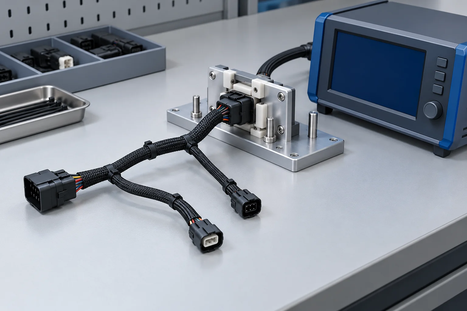
AI-generated inspection workflow concept; not a test record or photograph of OUKETECH equipment.
| Design or assembly risk | Verification to specify | Requirement to resolve before release |
|---|---|---|
| Wrong pinning or missing connection | Netlist-based continuity and connection mapping | Approved cavity numbering and connector viewing direction |
| Unintended connection | Defined shorts test | Expected isolated nets and intentional shared connections |
| Incorrect terminal crimp | Visual and dimensional checks; agreed destructive sample checks | Component-specific criteria, tools, and sampling |
| Insulation damage | Visual inspection and applicable electrical insulation testing | Approved limits and protection for connected components |
| Incorrect branch fit | First-article dimensional and equipment fit review | Datums, routing method, tolerances, and connector orientation |
| Intermittent failure during motion | Application-relevant qualification testing | Motion profile, mounting, environmental conditions, and acceptance limits |
9. Validate the Prototype in the Equipment and Control Revisions
Approve prototypes against electrical, dimensional, installation, and service requirements before releasing production. Record deviations and revise the controlled documents instead of approving undocumented sample changes. The production baseline should identify the drawing, bill of materials, pinout, test program, and any approved workmanship or packaging instructions that define the assembly.
For wire harness prototype to production planning, a successful bench connection is only one milestone. Install the sample in representative equipment, check assembly access, operate moving sections, and examine potential rubbing points. Verify that a technician can identify and disconnect the intended branch.
Capture issues with photographs and marked-up drawings, then issue a coordinated revision. A handwritten change to one branch can affect wire lengths, protective coverings, fixture dimensions, and test-adapter configuration. Require the supplier to acknowledge which revision the next sample will follow.
Separate prototype concessions from permanent production requirements. If a temporary connector or manual process is accepted for an early sample, specify its replacement and approval conditions. Procurement should confirm that the quoted production configuration matches the released design rather than the temporary prototype build.
10. Build an RFQ Package That Exposes Cost and Lead-Time Drivers
Send each supplier the same technical package and request a breakdown of recurring and one-time costs. Include prototype quantities, order quantities, expected annual usage, approved materials, test requirements, and packaging. A comparable quotation needs a common design baseline and a clear list of exclusions, assumptions, and unresolved engineering decisions.
For a custom wire harness assembly quotation, ask what drives the price beyond conductor length. Terminal count, breakout complexity, manual wrapping, inspection records, tooling, and special packaging can influence the manufacturing scope. Component availability can also govern the schedule even when assembly time is short.
Review value-engineering suggestions through the same approval process as other changes. Combining connector families or simplifying a breakout may reduce purchasing and assembly complexity. Such changes still need confirmation of electrical performance, fit, serviceability, and qualification implications.
| RFQ item | What the OEM should supply | What the supplier should clarify |
|---|---|---|
| Released technical baseline | Drawings, BOM, connection table, revision identifiers | Missing information and manufacturing assumptions |
| Materials and alternatives | Exact parts and approval rules for substitutions | Availability, minimum buy quantities, and alternative impacts |
| Quantities and schedule | Prototype, first order, forecast, and required dates | Component procurement and assembly schedule assumptions |
| Tooling and fixtures | Required outputs and ownership expectations | Separate charges, maintenance, storage, and change costs |
| Quality and testing | Applicable acceptance documents and test scope | Test coverage, sampling, records, and exclusions |
| Identification and delivery | Labels, packaging, routing protection, traceability needs | Packaging approach and shipment configuration |
FAQ
What files are needed for custom wire harness design and manufacturing?
Provide a schematic or connection table, dimensional drawing, bill of materials, connector and terminal part numbers, wire specifications, and acceptance requirements. Include mating-side references and equipment constraints. A physical sample can support the review, but uncontrolled sample details should be converted into documented requirements before production release.
Can an OEM request low-volume custom wire harness assemblies?
Yes, a low-volume project can be quoted, but tooling, component minimum orders, and inspection setup may dominate its economics. Ask suppliers to distinguish prototype work from repeat production and explain any minimum purchase commitments. Avoid assuming that a small assembly quantity eliminates one-time engineering or fixture costs.
Should every custom harness receive a dielectric withstand test?
The test plan should follow the application requirements and approved component limits. A dielectric withstand test is not automatically appropriate for every assembly, particularly one containing electronics. Specify the required method and acceptance criteria with the responsible engineering team rather than applying a generic test voltage.
How can buyers reduce wire harness cost without changing performance?
Start by removing ambiguity, avoiding unnecessary unique components, and using realistic tolerances. Request a manufacturing review of branch construction, wrapping, labeling, and assembly access. Evaluate proposed substitutions and process changes before approval. A lower piece price can be outweighed by qualification work, installation labor, or service costs.
How does a wire harness differ from a cable assembly?
A harness commonly organizes multiple wires and branches, while a cable assembly often uses a defined cable construction with terminated ends. Actual projects can combine both. When requesting custom cable assembly manufacturing, describe the physical construction and required interfaces so the supplier can scope the build accurately.
Discuss Your OEM Harness Requirements with OUKETECH
Established in 2010, OUKETECH is a commercial brand under Xinshao Electronic Technology Co., Ltd. The company supports custom wire harness design, prototyping, and manufacturing for OEM projects. Its custom wire harness and cable assembly services provide a starting point for discussing drawing-based builds and prototype-to-production requirements. Use the ten design checks above to prepare a package that supports a focused engineering discussion and a comparable quotation.
Send OUKETECH your drawings and RFQ requirements, including the BOM, connector and terminal part numbers, wire specifications, pinout, branch dimensions, sample quantity, annual volume, and test requirements. Identify unresolved design items so the quotation can distinguish confirmed requirements from assumptions that still need approval.