

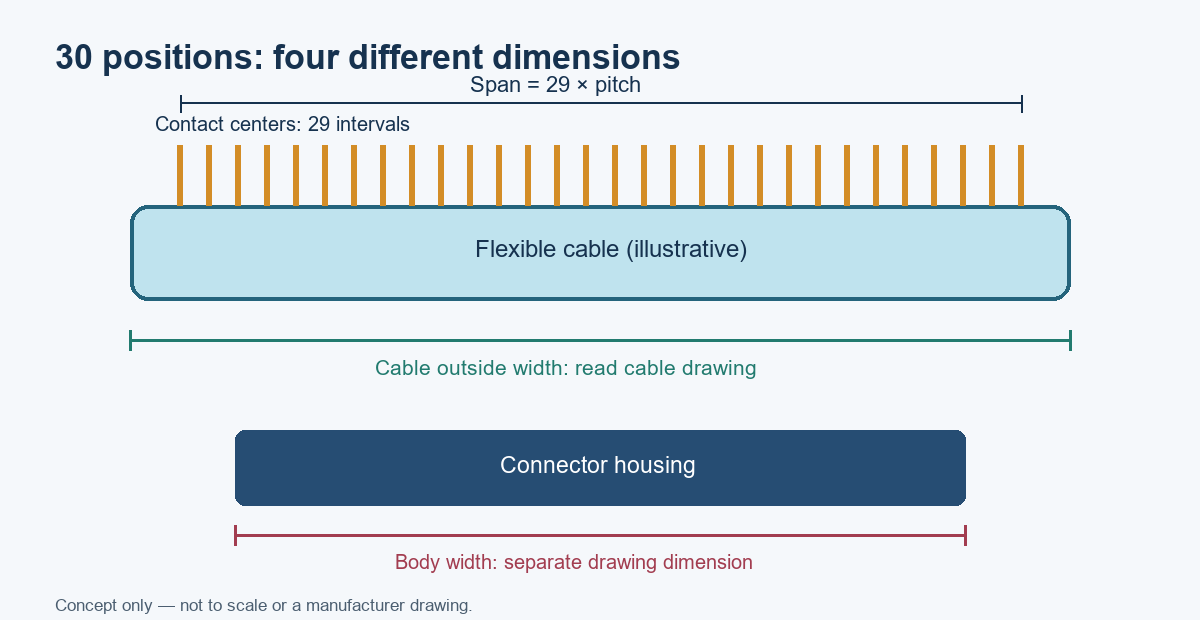
There is no single standard outside size for a 30-pin ribbon cable connector. “30-pin” usually identifies 30 conductive positions; it does not define pitch, cable width, connector body width, height, contact orientation, or latch geometry. For a 30-position connector with 0.50 mm pitch, the center-to-center span from the first to last contact is 14.50 mm, calculated as (30 − 1) × 0.50 mm. The actual body and cable dimensions must come from the exact part drawing.
That distinction matters when replacing a connector or laying out a printed circuit board (PCB). A cable can have the correct pin count and still fail to mate because its pitch, exposed-contact side, insertion direction, thickness, or stiffener differs.
What does “30 pin” tell you—and what does it leave out?
“30 pin” most often means a row of 30 contacts or circuits. It does not by itself identify an electrical interface or a mechanical envelope. Flexible flat cable (FFC) and flexible printed circuit (FPC) connectors may share a 30-position count while differing in pitch, actuation, mounting, and contact arrangement. Manufacturer catalogs show FFC/FPC families with multiple pitches and circuit counts, so the part number and drawing are essential for dimensional work. Molex’s FFC/FPC connector portfolio lists a broad pitch and circuit-count range.
The phrase “ribbon cable connector” can also describe a board-mounted FFC/FPC socket, a cable-mounted IDC connector, or a particular appliance replacement part. These are not dimensionally interchangeable. Confirm the connector technology and exact mating cable before ordering.
| Specification | What it identifies | Why it matters |
|---|---|---|
| Position or circuit count | Number of contacts/circuits in the row | Does not determine pitch or body size |
| Pitch | Center-to-center distance between adjacent contacts | Must match cable conductor spacing and connector series |
| Contact span | Distance between the first and last contact centers | Calculated from pitch and position count |
| Cable width | Physical width of the flexible cable | May include edge margins beyond the outer conductors |
| Connector body width | Housing’s outside dimension | Includes side walls, anchors, and actuator features |
| Cable thickness and stiffener | Cable stack and insertion reinforcement | Affects retention and insertion into the connector |
| Contact side and entry direction | Top/bottom contact and front/back insertion arrangement | Determines whether the cable’s exposed conductors face the contacts |
How do you calculate the contact span for 30 positions?
For a single row of evenly spaced contacts, the center-to-center span is (N − 1) × pitch, where N is the number of positions. There are 29 gaps between 30 contact centers, not 30 gaps. The result is a contact span only; it is not automatically the cable’s cut width or the connector’s outside width.
| Nominal pitch | Calculation for 30 positions | First-to-last contact-center span |
|---|---|---|
| 0.30 mm | 29 × 0.30 mm | 8.70 mm |
| 0.50 mm | 29 × 0.50 mm | 14.50 mm |
| 1.00 mm | 29 × 1.00 mm | 29.00 mm |
| 1.27 mm | 29 × 1.27 mm | 36.83 mm |
| 2.54 mm | 29 × 2.54 mm | 73.66 mm |
These values are geometry calculations, not a list of interchangeable 30-pin connector standards. A given product family may not offer every combination shown. Confirm the series’ supported position counts and the drawing before using a calculated span in a PCB footprint or cable specification.
The distinction between “span” and “width” is a common source of errors. A connector drawing may show a body-width formula that adds housing margins to the contact field. The cable drawing may define conductor pitch, edge margin, and finished width separately. Never treat the calculated contact span as the finished cable width unless the cable specification explicitly defines it that way.
Which dimensions should you read on the datasheet drawing?
Read the dimensional drawing for the exact manufacturer part number, not a distributor’s generic thumbnail. Manufacturer drawings provide the mechanical references needed to design the PCB footprint, specify the FFC/FPC, and check mating clearance. For example, TE Connectivity’s 30-position, 0.5 mm pitch FPC connector page identifies pitch, mounting orientation, contact location, and links a product drawing. Those details still apply only to that listed series and part.
| Drawing callout | Check | Typical mistake |
|---|---|---|
| Pitch / centerline | Contact spacing, measured center to center | Assuming the same 30 positions means the same spacing |
| Overall housing width | Maximum outer width and side features | Using contact span as the footprint width |
| Mating depth / insertion length | Cable insertion stop and exposed-contact length | Measuring only the visible cable tail |
| Height / mated height | Connector and actuator clearance | Ignoring the closed latch or cable bend above the board |
| Contact position | Top or bottom contact; same-side or opposite-side cable contacts | Ordering a cable with the wrong exposed-contact face |
| Cable thickness | Supported FFC/FPC thickness and tolerance | Assuming visually similar cables have the same stack-up |
| PCB land pattern | Pad locations, solder tabs, keep-outs, and recommended footprint | Creating pads from a photo or measuring the molded body |
| Actuator opening | Service and insertion clearance | Blocking a flip latch with a nearby enclosure wall |
If the connector is already installed, take measurements with the board unpowered and use magnification. Measure the contact-center span where practical, then divide by 29 to estimate pitch. That estimate can distinguish common pitch families, but it does not establish a valid replacement part. Verify against a part marking, service manual, PCB drawing, or connector manufacturer documentation.
Does “30 pin” mean the cable is 15 mm wide?
No. A 30-position cable at 0.5 mm pitch has a 14.5 mm contact-center span, which is close to 15 mm, but that is not enough to specify a 15 mm-wide cable. The finished cable width depends on conductor width, edge margins, and the cable maker’s dimensional definition. The mating connector may also require a specific width tolerance and stiffener arrangement.
Likewise, a 1.0 mm pitch 30-way cable has a 29 mm contact span. A common nominal width description may be rounded or based on a product family convention, but a design release needs the cable drawing and connector part number. Avoid ordering solely by a rounded width claim from a marketplace listing.
How can you identify an unknown 30-pin connector?
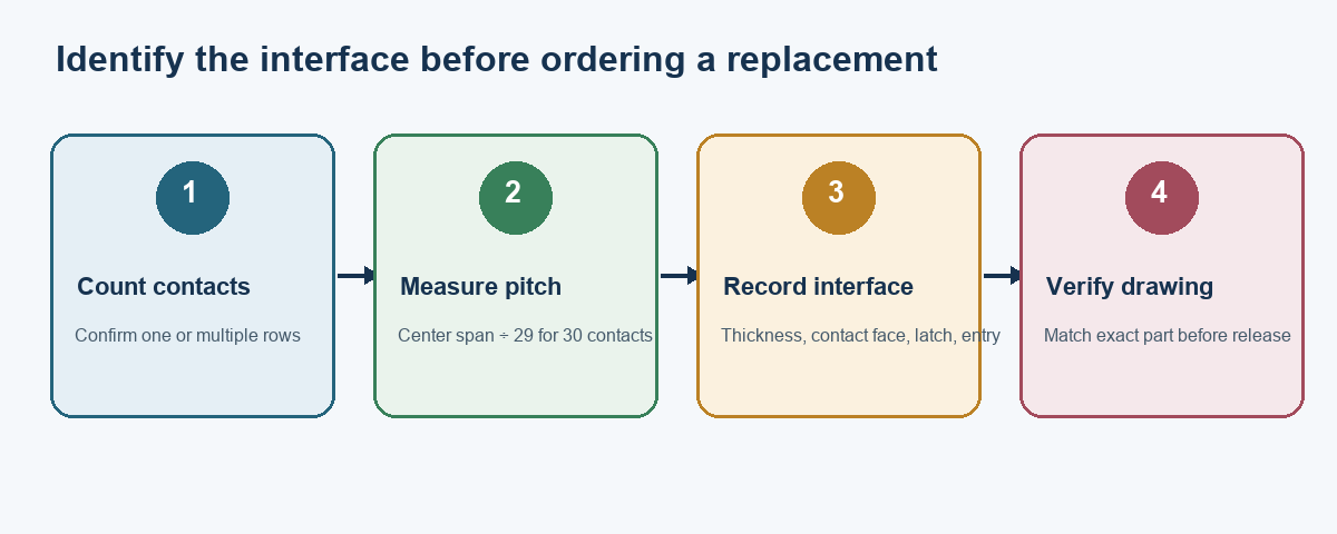
Start with the installed interface, not a guess based on appearance. Record the board and connector markings, count the contacts, determine the insertion direction, and inspect the exposed-contact face of the cable. Then compare measured pitch, cable thickness, latch style, and mounting orientation with manufacturer product drawings. If any dimension is uncertain, retain the original cable and connector for comparison rather than forcing a candidate part into place.
- Count positions. Confirm there are 30 conductive tracks/contacts, not 30 total positions split across two rows.
- Estimate pitch. Measure from the center of the first to the center of the last contact and divide by 29. A microscope or calibrated image helps reduce parallax.
- Record the cable. Measure width and thickness; note exposed-contact side, stiffener length, and insertion depth.
- Record the socket. Note top- or bottom-contact, front- or back-entry, ZIF (zero insertion force) or non-ZIF actuation, and right-angle or vertical mounting.
- Find the exact drawing. Search manufacturer markings and part numbers. Compare the recommended PCB land pattern and mating specifications.
- Check the electrical mapping. Verify pin 1, conductor order, cable orientation, and polarity before powering the assembly.
Do not use caliper pressure to compress a flexible cable or latch. Do not scrape contacts to reveal markings. Electrostatic-sensitive assemblies should be handled with appropriate ESD controls.
FFC, FPC, and IDC ribbon connectors: which type are you measuring?
The name “ribbon cable” covers different constructions. FFC is a flat flexible cable with parallel conductors laminated between insulating films. FPC generally refers to a flexible printed circuit, which may include patterned copper, coverlay, stiffeners, and custom shapes. IDC (insulation-displacement contact) ribbon cable systems use a different connector and termination method, often with larger spacing than compact FFC/FPC sockets. The correct terminology narrows the search, but the part drawing settles the dimensions.
| Interface | What to inspect | Dimensional risks |
|---|---|---|
| FFC with ZIF socket | Pitch, thickness, contact side, stiffener, insertion depth | Cable may be too thick or have contacts on the wrong face |
| FPC with ZIF socket | Contact layout, stiffener geometry, bend zone, socket family | A custom circuit outline may not match a straight FFC |
| FFC/FPC non-ZIF socket | Supported cable thickness, retention mechanism, insertion length | Friction-fit designs are sensitive to cable thickness and wear |
| IDC ribbon assembly | Row count, pitch, polarization, cable construction, termination | A 30-way IDC housing is not a 30-position FFC socket |
Molex and TE Connectivity publish individual family and part pages with supported configurations, drawings, and product attributes. Use these manufacturer resources to distinguish a connector family from a generic “30-pin” label: Molex FFC/FPC products and TE Connectivity FPC connectors.
What causes a 30-pin cable to fit poorly or fail after installation?
Poor fit often comes from treating dimensions as independent of the connector series. A cable may match pitch and pin count yet fail because the cable is too thick, too narrow, too short at the contact end, or reversed relative to the socket contacts. A latch can appear closed while the conductors remain partly outside the contact zone. Inspect the assembly without pulling on the cable and check the connector manufacturer’s assembly instructions.
| Symptom | Possible dimensional or configuration cause | Practical check |
|---|---|---|
| Cable will not enter | Incorrect pitch, width, thickness, stiffener, or insertion direction | Compare cable drawing and connector family specification |
| Latch will not close | Cable too thick, stiffener too long/thick, or cable not fully inserted | Check the supported thickness and insertion stop |
| Intermittent signals | Incomplete insertion, contamination, wrong contact face, damaged latch | Inspect retention and verify contact orientation and continuity |
| Connector overhangs PCB | Wrong series, body width, mounting orientation, or footprint | Compare the exact part drawing and recommended land pattern |
| Cable bends sharply at socket | Mating geometry or routing space is inadequate | Verify bend zone and provide clearance in the enclosure |
Avoid repeatedly cycling a damaged ZIF latch. Plastic actuators and cable contacts can be damaged by excessive force. For production, define a controlled work instruction, cable orientation check, and electrical test appropriate to the assembly. OUKETECH’s custom cable assembly service describes build-to-print review using customer drawings, bills of materials, pinouts, and test requirements; confirm the project’s specific connector and process scope during quotation.
What should you include in a replacement or manufacturing request?
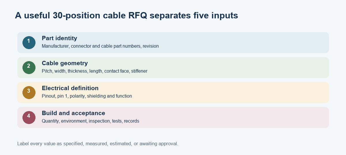
Provide enough controlled information for a supplier to distinguish the connector family and cable geometry. A photograph helps explain the installed configuration, but it cannot replace a part number or drawing. If the original component is obsolete or unidentified, label measurements as measured or estimated and ask for engineering review before approving a substitute.
Include these items in the request:
- Manufacturer and full connector part number, if known, plus the mating cable part number.
- Position count, pitch, cable type (FFC, FPC, or IDC), finished width, thickness, and tolerance.
- Cable length, exposed-contact length, stiffener material and dimensions, and contact-side orientation.
- Connector mounting style, contact location, actuator type, board footprint, and keep-out constraints.
- Pinout, pin 1 location, electrical function, and any polarity or shielding requirements.
- A dimensioned drawing or controlled sample, revision status, quantity, packaging, and delivery target.
- Required inspection, electrical test, traceability, and documentation criteria.
For an RFQ, OUKETECH’s guide to information required for a custom wire harness quote explains how drawings, a bill of materials, connector data, quantities, and test needs support a clearer review. The contact page accepts project inquiries. A quotation should identify assumptions and unresolved dimensions rather than silently selecting a substitute.
How OUKETECH can support a custom cable project
OUKETECH describes build-to-print cable assembly support based on customer drawings, samples, bills of materials, pinouts, and test requirements. That is relevant when a 30-position cable is part of a larger cable assembly or harness and the project needs sourcing, manufacturing, inspection, or documentation coordination. Final connector selection and dimensional approval remain tied to the released customer requirements and exact component documentation.
For a useful review, send the connector and cable part numbers, dimensional drawing, mating interface, pinout, quantity, application environment, and test plan. If part numbers are unavailable, include clear photographs from several angles and measured dimensions with measurement method and confidence noted. Use OUKETECH’s custom cable assembly page to start a project inquiry.
FAQ: 30-pin ribbon cable connector dimensions
What is the width of a 30-pin ribbon cable?
There is no single width. First determine the pitch: 30 contacts at 0.5 mm pitch span 14.5 mm from the first to last contact center. The finished cable width includes edge margins and follows the selected cable specification.
What is the pitch of a 30-pin FFC cable?
Pin count does not define pitch. A 30-position FFC/FPC connector may be offered in a particular family at 0.5 mm, 1.0 mm, or another supported spacing. Read the exact part number and manufacturer drawing.
How do I calculate 30-pin connector spacing?
For one row of 30 evenly spaced contacts, multiply the pitch by 29. For example, 0.5 mm pitch gives a 14.5 mm contact-center span. This is not the outside width of the connector housing.
Can I replace a 30-pin connector with any connector that has the same pitch?
No. The replacement must also match contact orientation, entry direction, actuator, mounting style, cable thickness, insertion length, electrical requirements, and PCB footprint. Confirm the exact mating system before substitution.
Is a 30-pin FPC cable the same as a 30-pin FFC cable?
Not necessarily. FFC is a laminated flat cable, while FPC may use a patterned flexible circuit and custom outline. The terms are sometimes used loosely in listings, so verify construction and the connector manufacturer’s compatibility data.
Which dimension should I measure first on an unknown connector?
Count the positions, then estimate pitch from the first-to-last contact-center span divided by 29. Also record cable thickness, contact face, insertion depth, and socket style. Use those measurements to locate documentation rather than as the only basis for ordering.