Table of Contents
- What Is a Coaxial Cable?
- How Coaxial Cables Work
- 50 Ohm vs 75 Ohm: The Two Impedance Camps
- Coaxial Cable Types
- Coaxial Cable Connector Types
- Where Coaxial Cables Get Used
- Coaxial vs Fiber Optic vs Twisted Pair
- How to Choose the Right Coaxial Cable
- Installation Tips That Prevent Callbacks
- Frequently Asked Questions
- The Bottom Line
What Is a Coaxial Cable?
A coaxial cable — coax for short — is a transmission line built to carry radio frequency (RF) signals from one point to another without turning into an antenna along the way.
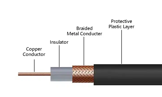
Inside every coax cable are four layers:
- Center conductor — Solid or stranded copper (sometimes copper-clad steel or copper-clad aluminum). This is where the signal travels.
- Dielectric insulator — A layer of polyethylene foam or solid PTFE that holds the center conductor precisely in place. The spacing between conductor and shield has to stay constant; if it doesn’t, impedance shifts and signal reflects.
- Metallic shield — Braided copper, aluminum foil, or both. This layer blocks external electromagnetic interference (EMI) and also serves as the return path for the signal.
- Outer jacket — PVC, PE, or fire-rated material. Protects the internals from moisture, UV, and physical damage.
The word “coaxial” means the center conductor and the outer shield share the same geometric axis. That’s not a marketing term — it’s the physics that makes coax work. Because the two conductors are concentric, the electromagnetic field stays contained between them instead of radiating outward.
Coax handles frequencies from roughly 20 kHz up to 300 GHz, depending on construction. That range covers everything from analog audio to millimeter-wave radar.
How Coaxial Cables Work
The center conductor carries the RF signal. The shield does two jobs at once: it blocks outside interference from getting in, and it keeps the signal from leaking out.
Between them, the dielectric maintains a fixed spacing. That spacing — combined with the dielectric material’s properties — determines the cable’s characteristic impedance, measured in ohms (Ω). For coax, this is almost always 50Ω or 75Ω.
Here’s why impedance matters: if you connect a 75Ω cable to 50Ω equipment, some of the signal bounces back toward the source instead of reaching the destination. This is called impedance mismatch, and it shows up as signal loss, ghosting on video, or data errors. The technical term for how bad the mismatch is — VSWR (Voltage Standing Wave Ratio) — tells you what percentage of signal is reflecting. A VSWR of 1.0:1 is perfect. A VSWR of 2.0:1 means about 11% of your signal never arrives.
The shield also prevents the cable from acting like an antenna. Regular wire carrying high-frequency AC will radiate energy into the air — that’s signal loss. The coaxial design traps the field between the center conductor and the inside surface of the shield. This is called the skin effect: at high frequencies, current travels only on the outer surface of the center conductor and the inner surface of the shield.
50 Ohm vs 75 Ohm: The Two Impedance Camps
Every coax cable falls into one of two impedance categories. Mixing them causes problems.
| Impedance | Typical Cables | Primary Use |
|---|---|---|
| 50 Ω | RG-58, RG-8, RG-213, RG-214 | Radio transmission (CB, ham, two-way radio), old 10BASE2 Ethernet, RF test equipment, cellular base stations |
| 75 Ω | RG-6, RG-59, RG-11 | Cable TV, satellite, broadcast video, CCTV, cable broadband, digital audio (S/PDIF) |
Why two standards? It’s a historical split. 75Ω happens to be the impedance that minimizes signal loss in a coaxial structure — ideal for receiving weak signals over distance. 50Ω is a compromise between power handling and low loss — better for transmitting. Broadcast and CATV went 75Ω. Radio transmission went 50Ω.
Don’t mix them. A 50Ω BNC connector looks identical to a 75Ω BNC connector. Plug the wrong one in and you’ll chase intermittent problems for hours. I’ve seen entire CCTV systems brought down by one mismatched connector in the chain.
Coaxial Cable Types
RG Series
RG stands for “Radio Guide,” a WWII-era military specification that’s been obsolete for decades. The numbers stuck around as industry shorthand. Today, “RG-6 type” means the cable follows the general blueprint of the original spec but uses modern materials.
Here’s how the four most common RG types compare:
| Specification | RG-6 | RG-59 | RG-11 | RG-58 |
|---|---|---|---|---|
| Impedance | 75 Ω | 75 Ω | 75 Ω | 50 Ω |
| Center conductor | 18 AWG | 20 AWG | 14 AWG | 20 AWG |
| Outer diameter | 0.332 in | 0.242 in | 0.405 in | 0.195 in |
| Attenuation @ 1 GHz | ~6.8 dB/100ft | ~9.5 dB/100ft | ~4.5 dB/100ft | ~10.5 dB/100ft |
| Primary use | CATV, satellite, internet | Short CCTV runs, analog video | Long trunk lines, outdoor | Radio, RF test, old Ethernet |
| Flexibility | Good | Excellent | Stiff | Good |
RG-6 is the workhorse. It’s in your walls carrying cable TV and internet. Available in four application-specific variants: standard (indoor), flooded (underground with water-blocking gel), messenger (with a steel support wire for aerial drops), and plenum (fire-rated jacket for air-handling spaces).
RG-59 was the TV antenna standard 40 years ago. Today it’s mostly CCTV and short analog video runs. Thinner and more flexible than RG-6, but higher loss at frequency.
RG-11 is the thick, low-loss option. Used for long outdoor runs and trunk distribution where you can’t afford an amplifier. Hard to work with — it doesn’t bend easily and won’t fit RCA connectors.
RG-58 is the 50Ω counterpart to RG-59. Common in ham radio setups, RF test leads, and legacy thin Ethernet. Not for video.
For a deeper dive into RG cable differences, see our RG6 vs RG58 vs RG59 vs RG11 comparison guide.
Hardline Coaxial Cable
Hardline cables use a solid metal outer conductor — typically aluminum or copper tubing — instead of braided shield. Center conductors range from copper-clad aluminum to solid copper tubing. Diameters start at ½ inch and go up.
These cables handle high power with very low loss. You’ll find them in:
- AM/FM broadcast tower feeds
- Cellular base station antenna lines
- Cable TV trunk distribution (the thick orange cables on utility poles)
- Military radar and communication systems
Some hardline cables use pressurized nitrogen or dry air inside the dielectric to prevent moisture ingress and arcing at high power levels.
Semi-Rigid and Hand-Formable Cable
Semi-rigid coax replaces the braided shield with a solid copper tube. The result: near-perfect shielding and excellent phase stability. The trade-off is flexibility — you bend it once during installation and it stays there.
Hand-formable cable is the compromise. It uses a tin-plated copper braid outer conductor that holds its shape after bending, giving you semi-rigid performance with easier installation.
These cables show up in:
- RF test and measurement (spectrum analyzers, network analyzers)
- Aerospace and satellite systems
- Medical imaging (MRI, CT scanner signal paths)
- Military electronics where phase-matched cable sets are critical
Radiating (Leaky) Cable
Radiating coax — also called leaky feeder cable — has slots cut into the outer shield at precise intervals. These slots let a controlled amount of RF signal leak out (or in) along the cable’s entire length.
The use case: places where antennas don’t work. Tunnels, mines, subway systems, underground parking garages, elevator shafts. Instead of trying to cover a 2-mile tunnel with discrete antennas, you run one leaky cable the whole way. Radios and cell phones connect to the cable as if it were a continuous antenna.
Twinaxial and Triaxial Cable
Twinax puts two center conductors inside one shield. This configuration supports differential signaling — the same principle behind balanced audio and Ethernet. Twinax handles high-speed data over short distances with excellent noise rejection. Common in:
- SFP+ and QSFP direct-attach cables for data centers (10G, 25G, 40G, 100G)
- Military avionics (MIL-STD-1553 data bus)
- Professional digital video (SDI)
Triax adds a second layer of insulation and a second shield outside the first. The outer shield connects to ground; the inner shield carries signal return. This gives you:
- Better noise rejection than standard coax
- Ability to carry power on the outer shield independently of the signal
- Common in broadcast TV cameras and studio equipment
Low-Loss, High-Temperature, and Specialty Cable
Low-loss coax uses larger center conductors, foam dielectrics with higher air content, and denser shielding to push attenuation numbers down. Common in cellular DAS (Distributed Antenna Systems) and long satellite runs. Popular series include LMR-200, LMR-400, and LMR-600 from Times Microwave.
High-temperature coax uses PTFE (Teflon) dielectric and FEP jackets rated for 200°C and above. Found in aerospace engine compartments, industrial furnaces, and down-hole oil drilling equipment.
Submarine coax uses armored jackets and longitudinal water-blocking to survive decades on the ocean floor. These cables powered the first transatlantic telephone systems before fiber took over.
Lightning-protection coax incorporates surge suppression layers to shunt induced lightning currents to ground before they reach equipment. Standard requirement for tower-mounted antennas and outdoor base stations.
For projects needing custom coaxial cable assemblies built to exact specifications — including specific lengths, connector types, and shielding requirements — factory-terminated cables eliminate the most common failure point in RF systems: field-installed connectors.
Coaxial Cable Connector Types
The connector is where most coax installations fail. Here’s a rundown of the common types and where they belong:
| Connector | Impedance | Frequency Max | Common Use |
|---|---|---|---|
| F-type | 75 Ω | ~3 GHz | CATV, satellite, cable modem |
| BNC | 50 Ω / 75 Ω | ~4 GHz | CCTV, test equipment, broadcast |
| TNC | 50 Ω | ~12 GHz | Cellular, outdoor RF (threaded, weatherproof) |
| N-type | 50 Ω | ~11 GHz | Base stations, high-power RF |
| SMA | 50 Ω | ~18 GHz | WiFi antennas, RF modules, GPS |
| SMB | 50 Ω / 75 Ω | ~4 GHz | Internal board connections, automotive |
| MCX | 50 Ω / 75 Ω | ~6 GHz | GPS receivers, TV tuner cards, compact devices |
| RCA | 75 Ω | ~10 MHz | Consumer audio/video |
| 7/16 DIN | 50 Ω | ~7.5 GHz | Cellular base stations, high-power transmission |
| QMA | 50 Ω | ~6 GHz | Quick-connect version of SMA |
Critical note on BNC: 50Ω and 75Ω BNC connectors look nearly identical. The 75Ω version has a slightly different dielectric geometry. Using a 50Ω BNC plug in a 75Ω jack creates an impedance bump that degrades signal. In broadcast and video, always verify you’re using 75Ω BNC connectors.
For F-type connectors — the threaded ones on the back of your TV and cable modem — compression fittings beat crimp fittings every time. Compression creates a 360-degree weather seal. Crimp connectors work until moisture gets in, and then you’re chasing intermittent signal loss that only shows up when it rains.
Where Coaxial Cables Get Used
Television and Broadcast
Cable TV runs on 75Ω coax from the headend to your living room. Satellite TV uses RG-6 from the dish LNB to the receiver. Broadcast studios use triax for camera connections and precision 75Ω coax for SDI video routing.
Broadband Internet
DOCSIS cable modems connect through the same RG-6 that carries TV. The upstream and downstream channels share the cable using frequency division — TV channels occupy the lower frequencies, internet data rides higher up.
Cellular and Wireless Infrastructure
Cell towers use 50Ω hardline and low-loss coax to connect base station equipment to tower-mounted antennas. In-building DAS (Distributed Antenna Systems) use plenum-rated coax to distribute cellular signals throughout commercial buildings.
Security and Surveillance
Analog CCTV runs on RG-59 or RG-6. Modern HD-over-coax systems (HD-TVI, HD-CVI, AHD) send 1080p and 4K video over the same RG-6 infrastructure, often paired with Siamese power cables. This is one reason coax-based CCTV refuses to die — upgrading cameras doesn’t require pulling new cable.
Aerospace and Defense
Semi-rigid and hand-formable coax fills avionics bays, radar systems, and satellite payloads. Phase-matched cable sets ensure signals arrive at exactly the same time across multiple paths. High-temperature coax handles engine sensor connections.
Medical Equipment
MRI machines, ultrasound systems, and patient monitoring equipment use precision coax for RF signal paths. Medical-grade coax often requires biocompatible jackets and sterilization tolerance.
Digital Audio (S/PDIF)
S/PDIF digital audio uses 75Ω coax with RCA connectors to carry stereo PCM or compressed surround sound between CD transports, DACs, and AV receivers. A proper 75Ω digital audio cable is electrically identical to a video coax — the “digital audio” label is mostly marketing. What matters is consistent 75Ω impedance.
For any of these applications, custom cable manufacturing ensures you get the right cable, right connector, right length — tested and ready to install.
Coaxial vs Fiber Optic vs Twisted Pair
Each transmission medium has its zone. Here’s when to use which:
| Coaxial Cable | Fiber Optic | Twisted Pair (Cat6/6A) | |
|---|---|---|---|
| Signal type | RF electrical | Light | Differential electrical |
| Max distance | ~1,500 ft (with amplification) | 40+ km (single-mode) | 328 ft (100 m) |
| Max bandwidth | ~3 GHz (RG-6), higher for specialty | Virtually unlimited | 500 MHz (Cat6A) |
| EMI immunity | Good (shield-dependent) | Excellent (immune) | Fair (depends on twist and shielding) |
| Cost per foot | Low | Medium to high | Low |
| Installation complexity | Low | High (termination requires skill) | Low |
| Power delivery | Yes (limited, via center conductor) | No | Yes (PoE up to 100W) |
| Best for | RF distribution, CATV, satellite, CCTV | Long-haul data, high-EMI environments | LAN, IP cameras, VoIP, office networks |
The practical rule: coax wins when you need to move RF signals (TV, satellite, radio, analog video). Fiber wins when you need bandwidth over distance. Twisted pair wins for local data networks and when you need to deliver power with data (PoE).
Coax and fiber increasingly coexist. Hybrid fiber-coax (HFC) networks use fiber for the long trunk runs and coax for the last mile into homes. This is how most cable ISPs deliver gigabit internet — fiber to the node, coax to the home.
For industrial cable solutions that combine multiple cable types in one harness — coax for RF, twisted pair for data, power conductors for DC — a single integrated assembly simplifies installation and reduces failure points.
How to Choose the Right Coaxial Cable
Four questions get you to the right cable every time:
1. What’s the impedance?
If your equipment says 50Ω, you need 50Ω cable. If it says 75Ω, you need 75Ω. There’s no flexibility here. Check the equipment specs, not the connector type — BNC connectors exist in both impedances.
2. What frequency are you running?
Low frequency (under 100 MHz): RG-59 or RG-58 works fine.
Medium frequency (100 MHz – 1 GHz): RG-6 is the standard choice.
High frequency (1 GHz – 3 GHz): RG-6 with solid copper center conductor, sweep-tested to 3 GHz.
Above 3 GHz: Look at low-loss cable (LMR-400, LMR-600) or semi-rigid.
3. How long is the run?
Under 100 feet: Standard RG-6 or RG-59.
100 – 200 feet: RG-6 with solid copper conductor.
200 – 500 feet: RG-11 or low-loss coax.
Over 500 feet: Consider fiber, or plan for amplification.
4. Where is it going?
Indoor, residential: Standard PVC jacket, dual or quad shield.
Outdoor, exposed: PE jacket with UV resistance. Waterproof all connections.
Underground: Direct-burial rated with gel-filled or dry water-blocking. Or run standard cable in conduit.
Plenum spaces (above ceilings, HVAC returns): Plenum-rated (CMP) jacket required by code. PVC-jacketed cable in plenum spaces is a fire code violation and a real safety hazard — burning PVC releases hydrogen chloride gas.
High-temperature: PTFE dielectric, FEP or silicone jacket.
For a broader overview of all cable types and their specifications, read our complete guide to coaxial cable types for 2026.
Installation Tips That Prevent Callbacks
Most coax problems aren’t cable defects. They’re installation errors.
Bend radius matters. The minimum bend radius for RG-6 is about 10 times the cable diameter — roughly 3.3 inches. Tighter bends crush the dielectric and create impedance bumps. Every impedance bump reflects some signal back toward the source.
Ground the shield — once. Outdoor coax runs must be grounded to the building’s grounding electrode system per NEC Article 820. This isn’t optional. Ungrounded outdoor coax is a lightning path into your equipment rack. Use a proper grounding block, not a screw into a random pipe.
Waterproof everything outside. Water inside coax travels along the braid by capillary action. A pinhole in the jacket at the roof penetration can wick moisture 50 feet down the cable into your equipment. Use weather boots or self-amalgamating tape on every outdoor connector. Install drip loops so water runs off the cable instead of following it into the building.
Compression connectors, not crimp. Compression F-connectors create a 360-degree seal. Crimp connectors have gaps. Spend $30 on a compression tool — it pays for itself the first time you don’t have to re-terminate a connector in a hot attic.
Test before you close the wall. A simple continuity test with a multimeter catches shorts and opens. For critical installations, a TDR (Time Domain Reflectometer) shows you exactly where impedance problems are along the cable — down to the foot. This is standard practice in cellular and broadcast installations and worth doing for any permanent in-wall run.
Sweep test your cable. Quality coax comes with a sweep test report showing attenuation across the full frequency range. If your supplier can’t provide sweep data, assume the cable hasn’t been tested. Dead spots at specific frequencies are common in cheap cable and nearly impossible to diagnose after installation.
For large-scale or mission-critical installations, having custom cable assemblies factory-built and tested eliminates field termination errors entirely. If you need help specifying the right cable for your project, contact our engineering team.
Frequently Asked Questions
Q: What’s the difference between RG-6 and RG-6/U?
Nothing meaningful. The “/U” suffix originally meant “universal utility” in the WWII-era military spec. Modern manufacturers use both markings interchangeably. Focus on the actual specifications — conductor material, shielding type, sweep test data — not the suffix.
Q: Can I use 50-ohm coax for TV or cable internet?
No. TV and cable internet equipment expects 75Ω impedance. Using 50Ω cable creates an impedance mismatch that causes signal reflections, ghosting, and data errors. The connector might physically fit (BNC comes in both impedances), but the electrical mismatch will degrade performance.
Q: How long can I run RG-6 before I need an amplifier?
For cable TV: about 150 feet. For satellite: 100-150 feet. For OTA antenna: depends on signal strength, but 100-200 feet is typical. The attenuation table tells the story — at 1 GHz, you lose about 6.8 dB per 100 feet. Every 3 dB halves your signal power.
Q: Is RG-6 good enough for 4K TV?
Yes. RG-6 handles the frequency range used by cable and satellite 4K signals. The cable doesn’t know or care about resolution — it cares about frequency. As long as the signal stays within the cable’s rated bandwidth and the run length is reasonable, RG-6 works for 4K, 8K, and whatever comes next.
Q: What’s the difference between dual-shield and quad-shield RG-6?
Dual-shield has one foil layer and one braid (typically 60% coverage). Quad-shield has two foil layers alternating with two braids (60% + 40% coverage). Quad-shield provides better EMI rejection — useful near power lines, fluorescent lights, or in commercial buildings with dense cable trays. For most residential installations, dual-shield is sufficient.
Q: Can I run coax and electrical cable through the same hole?
No. NEC requires at least 2 inches of separation between coax and parallel AC power cables. Crossing at 90 degrees is acceptable. Running them together induces 60 Hz hum into the coax. In plenum spaces, the separation requirements are stricter.
Q: Does a more expensive coax cable actually make a difference?
Yes — to a point. The difference between a $20 no-name spool and a $60 Belden or CommScope spool is real: better shielding coverage, more consistent dielectric, actual sweep testing. The difference between a $60 Belden and a $200 “audiophile” coax with exotic branding is mostly marketing. Buy from manufacturers that publish specs, not stories.
Q: When should I switch from coax to fiber?
When your run exceeds 500 feet, when you need more bandwidth than coax can provide, or when you’re in an environment with extreme EMI (factory floors with VFDs, near MRI machines, lightning-prone outdoor runs). Fiber is immune to electromagnetic interference and doesn’t conduct electricity — both major advantages in harsh environments.
For more technical guides on cable types, connectors, and installation, visit our blog.
The Bottom Line
Coaxial cable isn’t glamorous technology. It’s been around since before World War II. But it works, it’s affordable, and for RF signal distribution, nothing else does the same job at the same price.
The key to a successful coax installation is matching the cable to the application: right impedance, right shielding, right jacket for the environment, and connectors installed correctly. Skip any of those four and you’ll be back troubleshooting.
For standard residential TV and internet: RG-6, dual-shield, compression F-connectors. For long outdoor runs: RG-11 or low-loss coax with proper grounding and waterproofing. For anything mission-critical: buy quality cable with published specs, test before closing walls, and consider factory-terminated assemblies to eliminate field failures.
Need custom coaxial cable assemblies built to your specifications? Contact our engineering team — we’ll help you spec the right cable and deliver it tested and ready to install.