

A dependable wire harness starts with a controlled build package and ends with evidence that the finished assembly matches it. The wire harness assembly process connects design intent to repeatable production through material control, wire preparation, termination, connector loading, routing, protection, and inspection. Each operation has its own checks, and the right sequence depends on the drawing, components, environment, and agreed acceptance criteria. This guide explains the eight main steps and the decisions that engineers and OEM buyers should settle before production.
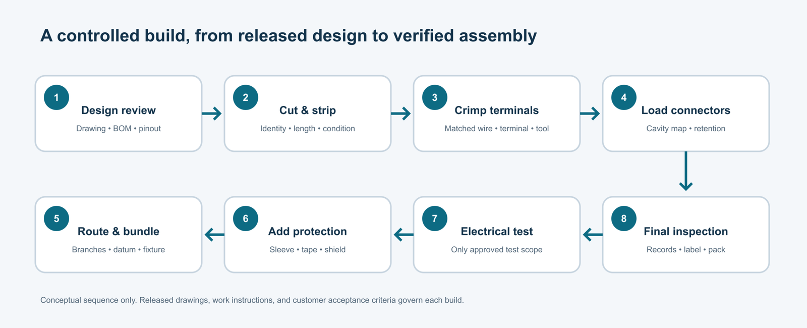
Illustration: a conceptual process map; actual operations vary by design and approved work instructions.
What Is a Wire Harness Assembly?
A wire harness assembly is an organized electrical interconnect made from insulated wires, terminals, connectors, and specified protective or identification components. It routes power and signals between defined points while helping equipment builders install multiple circuits as one controlled assembly. Harness construction does not by itself guarantee electrical or mechanical performance; those outcomes depend on correct design inputs, compatible components, process controls, and verification against project requirements.
Unlike a single cable assembly, a harness often contains multiple wires, branches, and termination points. It may use tape, braid, sleeve, conduit, clips, labels, or strain relief where the design calls for them. The final configuration can be simple, such as a short two-branch lead, or include many connector families and separately identified circuits.
Three documents commonly anchor the build: the released drawing, the bill of materials (BOM), and the pinout or connection list. They should agree on wire type and gauge, cut lengths, branch dimensions, terminal and connector part numbers, cavity assignments, labels, and revision. A sample may clarify fit or appearance, but it should not silently replace a controlled drawing. If the source documents conflict, resolve the discrepancy before cutting production material.
The assembly also needs defined acceptance criteria. IPC/WHMA-A-620 is an industry consensus reference for materials, methods, tests, and acceptability of cable and wire harness assemblies. It does not automatically define every product-specific test, inspection frequency, or customer requirement. The buyer and supplier should identify the applicable revision, class or acceptance level when relevant, and any additional drawing or contract requirements. See the IPC/WHMA-A-620 overview.
Wire Harness Assembly Process Overview: Step-by-Step Breakdown
The eight-step wire harness assembly process moves from approved engineering information to a verified, packaged product. The sequence is a useful baseline, not a universal recipe: some builds require soldering, shield termination, potting, overmolding, or intermediate tests, while others do not. Before work begins, define the record that proves each critical operation was completed and the criteria used to accept it.
| Step | Main input | Main control or evidence | Typical risk if missed |
|---|---|---|---|
| 1. Design and engineering review | Drawing, BOM, pinout, sample, requirements | Revision-matched build package and open-item resolution | Wrong materials, ambiguous dimensions, incompatible components |
| 2. Wire preparation | Approved wire and cut list | Cut length, strip length, conductor and insulation condition | Wrong length, nicked strands, damaged insulation |
| 3. Crimping and terminal connection | Terminal, wire, applicator/process specification | Setup approval, visual checks, dimensional or pull checks as specified | Loose, over-crimped, or misapplied termination |
| 4. Connector and subassembly build | Connector housing and cavity map | Terminal retention, seal/orientation, cavity verification | Backed-out or misplaced contacts, wrong keying |
| 5. Routing and harness assembly | Formboard, routing drawing, clips and branches | Branch dimensions, breakout positions, bundle sequence | Misrouting, twist, tension, fit problems |
| 6. Protection and insulation | Sleeve, tape, conduit, heat shrink, shield parts | Coverage, overlap, placement, clearance | Abrasion, contamination, blocked access, heat damage |
| 7. Testing and electrical checks | Approved test plan and pinout | Recorded continuity and any specified isolation/functional tests | Open circuit, short, swapped pin, undetected functional fault |
| 8. Final quality control and release | Acceptance criteria, labeling, packaging instructions | Inspection record, revision and quantity reconciliation | Mixed revisions, wrong identification, shipping damage |
Step 1: Design and Engineering Review
The review converts customer intent into executable manufacturing information. Confirm drawing revision, wire and cable specifications, gauge, color, cut length, connector and terminal part numbers, pin assignments, branch dimensions, labels, protection, environmental conditions, target quantity, and required tests. Review the BOM for approved alternates and availability constraints. Any substitution needs approval through the agreed change process.
Check that the pinout is unambiguous from the same viewing direction used on the drawing. Confirm connector keying, cavity numbering, wire-entry orientation, seal requirements, and mating parts. Flag dimensions without tolerances, unclear breakout locations, unsupported bend or routing assumptions, and conflicting sample details. Design for manufacturing (DFM) feedback is useful when it identifies a concrete risk, such as a terminal that does not match the conductor construction or a branch length that cannot be measured consistently.
The output should be a revision-controlled package: released drawing, BOM, pinout, work instructions, inspection points, and test requirements. For a prototype, open questions may be logged for evaluation. For repeat production, unresolved interpretation should not be left to operator judgment. OUKETECH’s custom cable assembly workflow describes the types of inputs used to review and plan build-to-print assemblies.
Step 2: Wire Preparation (Cutting and Stripping)
Wire preparation establishes the conductor length and exposed end needed for the specified termination. Operators or automated equipment cut each wire to the released length, then remove only the insulation required for the terminal or splice. The correct settings depend on wire construction, insulation material, gauge, and tooling; there is no single strip length or cut tolerance suitable for every harness.
Verify wire identity before processing. Mixed colors or gauges can be difficult to distinguish after a bundle is formed, so use controlled reels, clear job travelers, and in-process identification where needed. Check cut length with a defined measurement method, including whether the dimension runs from end to end, terminal shoulder to terminal shoulder, or another datum. For stripped ends, inspect for cut or missing strands, insulation damage, excessive exposed conductor, and debris.
High-mix production needs special attention to job changes. A correctly set machine can still process the wrong wire if the reel, recipe, or cut list is incorrect. First-piece approval after setup and a clear separation of completed and unprocessed wire reduce that risk. Labeling or temporary bundle control should preserve identity through later operations without contaminating the finished harness.
Step 3: Crimping and Terminal Connection
A crimp creates an electrical and mechanical connection by deforming a compatible terminal barrel around a conductor using the specified tool or applicator. The terminal, wire construction, and tooling must be an approved combination. Crimp appearance alone cannot establish that a termination meets every requirement; setup control and the project-defined inspection or test plan provide the relevant evidence.
Before running a lot, confirm terminal part number, wire gauge and strand construction, applicator identification, press setup, and any required conductor or insulation support. Verify the first piece using the criteria selected for the job. Depending on the specification, this may include visual features, crimp height or width, conductor brush and bellmouth, insulation support, and a pull-force check on a sample or setup piece. Do not invent a universal crimp-height or pull-force value; use terminal-application data, the customer drawing, and the approved workmanship criteria.
Watch for common defects: missing or cut strands, insulation caught in the conductor crimp, conductor outside the wire barrel, deformed terminal wings, cracks, wrong terminal orientation, and damaged plating. If a crimp is defective, follow an approved replacement or rework procedure. Recrimping a damaged terminal or adding solder to rescue an unsuitable crimp can create a new failure mode and should not be improvised.
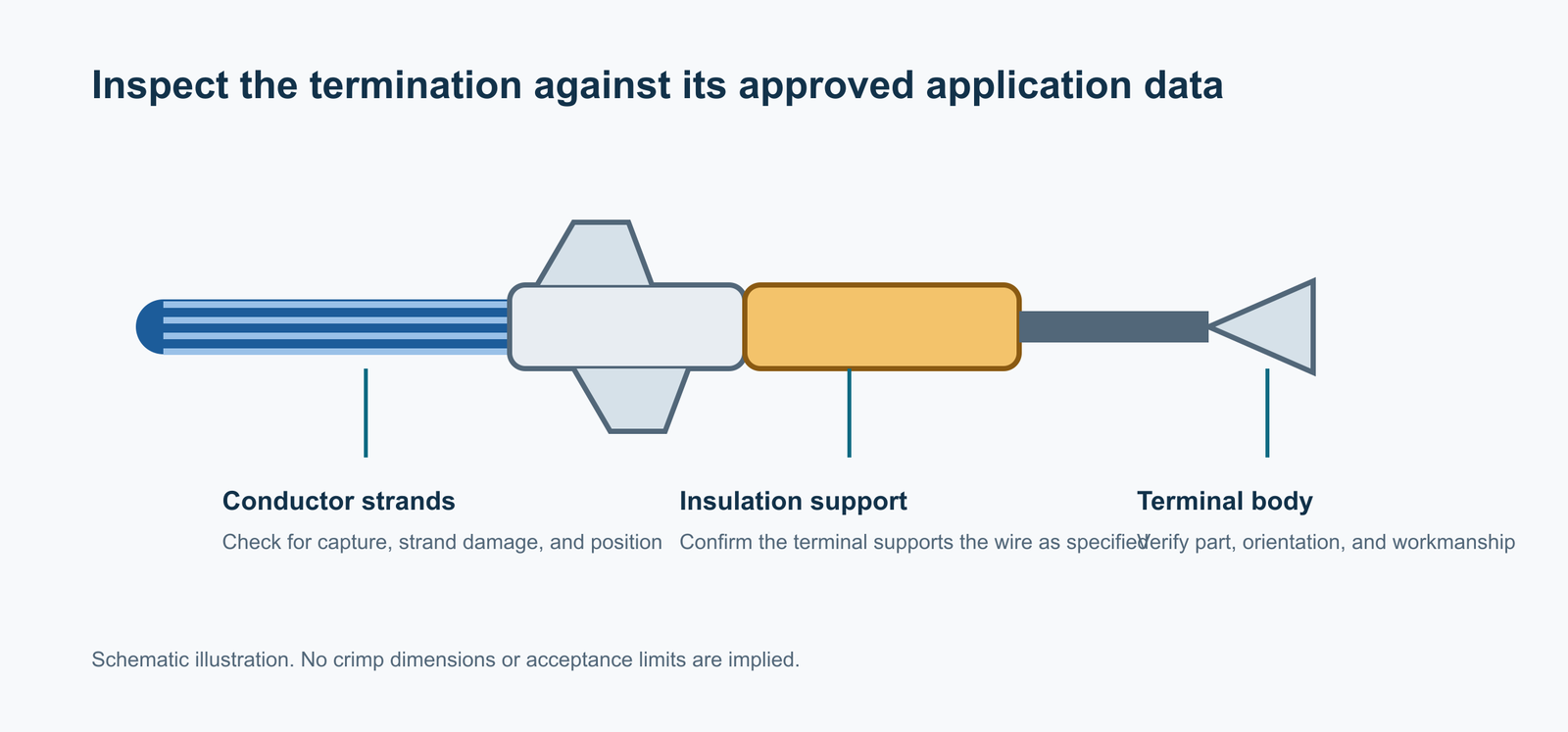
Schematic illustration only; use the approved terminal application data and acceptance criteria for inspection.
Step 4: Connector Insertion and Subassembly Assembly
After termination, contacts are inserted into their assigned connector cavities and subassemblies are built according to the pinout and assembly sequence. This step controls both electrical mapping and mechanical retention. Correct terminal insertion should be confirmed through the specified visual, tactile, or fixture-based method; the particular check depends on connector design and work instructions.
Match cavity numbering and connector orientation to the released view. A mirrored drawing interpretation can swap circuits even when each terminal is fully seated. Verify seals, plugs, locks, secondary locks, backshells, and other connector components in the specified order. Where more than one subassembly looks similar, maintain traceable identification until the units are joined.
An approved continuity or pin-mapping check at this stage can detect an early misload before the full harness is protected. It does not replace the final test unless the control plan explicitly defines it that way. The process record should show which connector configuration and revision were built, especially when variants share a common housing but use different cavity assignments.
Step 5: Routing and Wire Harness Assembly
Routing arranges wires along the drawing, assembly board, or defined fixture so that branch points, lengths, and connector exits match the intended installation. The build should preserve the specified path without forcing wires into place. Excessive tension, sharp bends, uncontrolled twisting, or branches formed at inconsistent locations can create assembly difficulty and mechanical stress in the installed equipment.
Use a formboard or fixture when it improves repeatability, and keep its revision aligned with the product definition. Route wires in the sequence that avoids crossing or trapping circuits, then apply specified ties, clips, tapes, or temporary holding points. Measure branch lengths from the defined datum. Check that connectors face the correct direction and that service loops, if required, remain within the drawing limits.
Routing is application-dependent. A stationary control cabinet, a vibrating machine, and moving robotic equipment expose wiring to different mechanical conditions. The design should specify bend, support, movement, separation, and clearance requirements where needed. If installers must bend or twist a harness beyond the natural route to make it fit, stop and resolve the discrepancy instead of treating force as an assembly aid.
Step 6: Protective Covering and Insulation
Protective covering is selected and applied to meet the documented abrasion, temperature, fluid, electrical, environmental, or handling needs of the assembly. Common options include tape, braided sleeve, corrugated conduit, heat shrink, shields, grommets, and overmolding. These are not interchangeable: material compatibility, coverage, flexibility, routing space, and service access all affect selection.
Apply protection at the locations and lengths shown in the drawing or work instructions. Confirm that it does not obstruct connector locks, labels, mounting features, drains, or required inspection areas. Heat-shrink processes need controlled positioning and heating so the insulation or adjacent components are not damaged. Shield terminations and drain wires should follow the circuit design; adding a shield connection without authorization can alter grounding or signal behavior.
Protection cannot correct a poor route or incompatible wire specification. It can also hide defects, which is why relevant inspections should happen before the harness is fully wrapped or closed. For builds with overmolding or potting, define any required pre-mold electrical check and dimensional review because access to internal terminations may be limited after the process.
Step 7: Testing and Electrical Checks
Testing verifies the characteristics named in the approved test plan. A common baseline is a continuity and short-circuit check against the pinout, but some products require insulation resistance, dielectric withstand, contact resistance, functional checks, or additional mechanical and environmental validation. The appropriate test depends on circuit design, voltage, components, application risk, and customer requirements.
The test fixture must map the correct connector cavities and prevent ambiguous results from poor contact. Confirm fixture identity and program revision, define handling for a failed unit, and keep retest rules clear. A continuity tester can find opens, shorts, and certain miswires; it does not prove that a harness will survive vibration, carry its rated current under actual conditions, or meet an untested environmental requirement. A passed test is evidence only for the checks it performs.
High-voltage or insulation tests require careful selection of test points and limits, especially where electronics, suppressors, sensors, or sensitive components remain connected. Do not apply a generic hipot value across every harness. The product owner and supplier should approve the test method, voltage, duration, ramp, and acceptance limits when those tests are required. Record results at the level agreed for the order, such as unit-level pass/fail, batch records, or measured values.
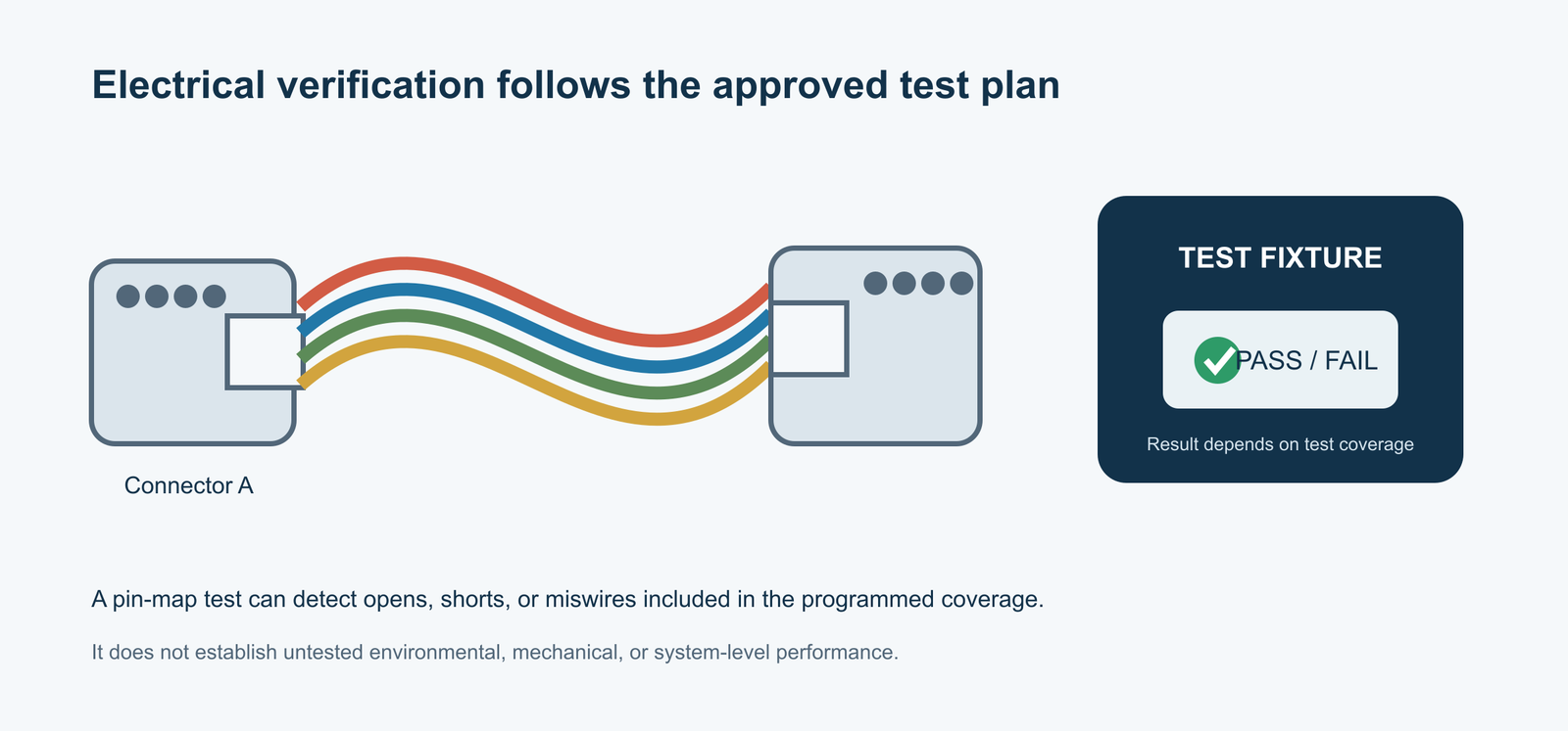
A fixture verifies only the checks covered by its approved program.
Step 8: Final Quality Control and Assurance
Final quality control checks that the completed harness matches the released definition and is ready for shipment. Review dimensions, branch locations, connector orientation, terminal seating, workmanship, labels, protection, test status, quantity, and packaging. Inspection criteria and frequency should be defined in the purchase requirements or control plan rather than assumed from a generic statement such as “100% inspection.”
Use a defect-response process that identifies the affected lot, contains suspect product, records the failure, and controls rework or disposition. A useful record links product identity to drawing revision, material or lot information when required, inspection status, test result, and approved deviation. Traceability depth should reflect customer, regulatory, and risk requirements; it is not automatically the same for every application.
Before release, reconcile the shipping label and packing list with the order, part number, revision, quantity, and any special packaging instructions. Protect connectors and branches from crushing, moisture, and tangling during transport. For repeat programs, retain the approved golden sample or inspection reference only when the customer and supplier have defined how it is controlled and superseded.
Where defects appear and how controls catch them
| Defect | Likely process point | Detection method to specify | Prevention control |
|---|---|---|---|
| Wrong cut length | Wire preparation | Datum-based measurement or approved gauge | Revision-controlled cut list; first-piece check |
| Nicked strands or damaged insulation | Stripping | Visual inspection under defined conditions | Tooling setup and blade condition control |
| Poor or wrong crimp | Termination | Approved visual/dimensional criteria; pull check when specified | Match terminal, wire, and applicator; setup approval |
| Wrong cavity or backed-out contact | Connector loading | Pin-map test and retention/visual check | Cavity map at station; orientation control |
| Incorrect branch dimension | Routing | Fixture or drawing-based measurement | Board revision control; stable datum and sequence |
| Open, short, or miswire | Assembly/test | Programmed electrical test | Verified pinout and fixture/program revision |
| Missing sleeve or misplaced label | Protection/final inspection | Visual and dimensional check | Operation sign-off; packaging/release checklist |
Wire Harness Assembly Applications
Wire harness assemblies are used wherever equipment needs multiple electrical circuits organized into an installable interconnect. Applications include industrial automation, vehicles and off-highway equipment, medical devices, lighting, telecom, energy systems, and specialized machinery. The process sequence remains recognizable across sectors, but wire, connector, protection, documentation, and validation needs vary with operating conditions and customer requirements.
| Application context | Design conditions to resolve | Process emphasis |
|---|---|---|
| Industrial machinery and automation | Vibration, routing, maintenance access, motor and sensor circuits | Branch positioning, retention, labels, and application-specific testing |
| Automotive and off-highway equipment | Temperature, vibration, fluids, variant control, service life | Approved components, revision discipline, traceability, and fit checks |
| Medical equipment | Device-specific risk, cleaning, material, and documentation needs | Controlled configuration and requirements agreed with the device maker |
| Robotics and moving equipment | Repeated flexing, bend path, motion range, torsion | Dynamic routing validation and suitable cable construction |
| Energy and battery systems | Voltage/current, separation, protection, connector compatibility | Defined electrical test plan and safe handling requirements |
| Telecom and data equipment | Shielding, impedance-sensitive paths, signal integrity | Correct cable/connector combination and project-specific performance checks |
For industry-specific requirements, review the relevant OUKETECH pages for industrial wire harnesses, automotive harnesses, and medical wire harnesses. These pages describe application areas; the customer’s drawings and agreed specifications govern an individual order.
Why Quality Control Matters in Wire Harness Assembly
Quality control matters because small process errors can become difficult-to-diagnose equipment faults after a harness is installed or covered. A wrong cavity, marginal crimp, damaged conductor, or incorrect branch length may cause intermittent operation, failed installation, service delay, or rework. Effective controls prevent defects where practical and create enough evidence to determine what was built and whether it met the agreed acceptance criteria.
The strongest control plan connects each important product characteristic to a process and a verification method. For example, a pinout requirement maps to a connector-loading instruction and electrical test; a branch dimension maps to a fixture or measurement; a crimp requirement maps to approved terminal data, setup checks, and defined inspection. This mapping prevents vague checks that do not reveal whether the critical characteristic was actually evaluated.
Quality planning should also scale with production pattern. A prototype build is a chance to confirm fit, clarify the drawing, and expose tooling or assembly issues. A small-batch run needs controlled setup and clear lot identity. High-mix production requires strong variant separation and job-change discipline. High-volume production benefits from repeatable tooling and sampling or monitoring plans that are agreed with the customer. None of these volume types eliminates the need for approved requirements.
Ask a supplier to explain how it controls revisions, approved substitutions, setup approval, defects, rework, electrical-test coverage, and release records. OUKETECH’s manufacturing and quality information describes build-to-print project support and quality controls; confirm the documents and test scope applicable to your specific assembly during qualification. A relevant supplier comparison should use project evidence, not broad claims alone.
Advantages of OUKETECH’s Wire Harness Production Process
OUKETECH presents its production approach as a coordinated flow from engineering review through preparation, termination, assembly, electrical verification, and packaging. For buyers, the practical value is having project inputs and acceptance needs discussed before production planning. The published process is a capability description; specific operations, records, capacity, tests, and certifications should be confirmed against the project and current qualification documents.
The OUKETECH wire harness manufacturing overview describes support for prototypes, high-mix orders, and volume production, with build-to-print inputs such as drawings, BOMs, pinouts, and specifications. The industrial harness page also outlines process stages including engineering review, wire preparation, crimping, subassembly, protective sleeving, electrical checks, inspection, and packaging. These published descriptions are useful starting points, not substitutes for the released work package or a supplier audit.
For an initial review, prepare the latest drawing, BOM, pinout, wire and connector requirements, target quantity, intended application, sample or fit requirements, and requested inspection or test evidence. Identify which items are mandatory and which allow an approved alternative. A clear RFQ helps the manufacturer identify ambiguities early and quote the actual process, tooling, inspection, and packaging scope.
If you are evaluating a build, send the specification through OUKETECH’s contact page or begin with the custom cable assembly service. Ask for a DFM review and quotation based on the released requirements, including prototype, small-batch, high-mix, or high-volume needs as applicable.
FAQ
How long does wire harness assembly take?
Lead time depends on drawing completeness, component availability, tooling, test fixtures, sample approval, order quantity, and production scheduling. Request separate timing for engineering review, prototype, approval, and repeat production rather than assuming one standard cycle.
Which tests should a wire harness receive?
At minimum, the agreed plan should address the electrical connections required by the design. Continuity and short checks are common, while insulation resistance, dielectric withstand, functional, mechanical, or environmental tests should be selected for the application and specified limits. Avoid applying a generic test voltage or acceptance value without engineering approval.
Does IPC/WHMA-A-620 specify every customer requirement?
No. It provides industry requirements and acceptance criteria for cable and wire harness assemblies, but a project still needs a drawing, component definitions, acceptance level where applicable, and product-specific test and documentation requirements. Buyers should state the applicable revision and any additions in the contract documents.
What should I send for a wire harness quotation?
Provide the current drawing, BOM, pinout, wire and connector part numbers, target quantity and release pattern, application environment, required standards or workmanship criteria, testing, labeling, packaging, and documentation needs. Include an approved sample when it adds information, while keeping drawing revision control authoritative.
Can a wire harness design change after production starts?
Yes, but the change should pass through a documented approval and revision process. Evaluate affected materials, tooling, test programs, inventory, work instructions, and units already in production before releasing the new configuration.