

Flexible Multi Conductor Cable: What It Is
A flexible multi conductor cable groups two or more insulated conductors under a common jacket and is designed to bend or move within defined application limits. “Multi conductor” describes the number of conductors; “flexible” describes the behavior of a particular construction under a stated bend radius, motion pattern, speed, temperature, and service life. The phrase alone does not establish a cable’s suitability for repeated motion.
The cable may carry power, control signals, low-level analog signals, or combinations permitted by the design. It can be supplied as bulk cable or built into a custom cable assembly with connectors, labels, branches, protective sleeving, or other specified features. Product selection should begin with the circuit and motion requirements, not just the keyword on a catalog page.
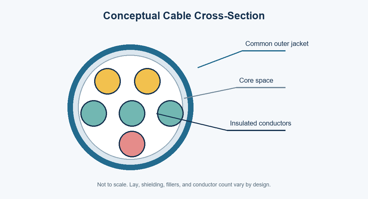
Conceptual diagram only; actual conductor count, lay, shielding, fillers, and jacket construction vary by design.
Multi Conductor, Multicore, and Flexible: What the Terms Mean
“Multi conductor” and “multicore” commonly refer to multiple insulated conductors within one cable. Usage differs across regions and product families, so confirm the manufacturer’s construction drawing. Neither term alone tells you conductor gauge, strand count, insulation, shielding, voltage rating, or motion life.
Flexibility is also not one standardized performance level. A finely stranded conductor may bend more readily than a solid conductor of the same nominal area, but conductor stranding alone cannot predict full-cable flex life. Core lay, fillers, insulation, shield, jacket, cable diameter, installation restraint, bend radius, and motion profile all affect the assembly. UL’s wire and cable application guidance explains that cable designations communicate construction and intended use; check the markings and applicable product documentation rather than assuming a generic name is an approval. UL Wire and Cable Application Guide
| Term | What it tells the buyer | What it does not establish |
|---|---|---|
| Multi conductor / multicore | More than one insulated conductor is grouped in one cable construction | Flex life, voltage class, shield performance, or current capacity |
| Flexible cable | Some bendability is intended for the specified construction | Continuous-flex suitability or an exact cycle rating without test data |
| Fine-stranded conductor | Conductor consists of multiple smaller strands and can be more pliable in handling | Whole-cable bend radius, drag-chain rating, or fatigue life |
| Shielded cable | A conductive layer is included to manage electromagnetic coupling under defined conditions | Guaranteed noise immunity in every installation |
| Continuous-flex cable | The cable is designed and qualified for a specified dynamic motion application | Suitability outside the stated machine, radius, speed, temperature, and test conditions |
Common Constructions and When to Consider Them
Flexible multi conductor cable constructions vary by conductor arrangement, insulation and jacket materials, shielding, and protective layers. A simple unshielded cable may be sufficient for low-noise fixed routing. A shielded, twisted, or individually screened design may be appropriate when signal integrity or electromagnetic compatibility requirements call for it. A cable for a moving machine axis may need a construction specifically designed and validated for that motion.
The cable should match its electrical function. Power conductors may need larger cross-sections and suitable voltage insulation. Signal conductors may need pair twisting, separation, or shielding to limit interference. If power and signals share one jacket, the designer should confirm separation, coupling, temperature rise, and applicable approvals for the equipment. A product sold as “multi conductor” is not automatically suitable for combining unrelated circuits.
| Construction choice | Typical reason to consider it | Key questions before release |
|---|---|---|
| Unshielded stranded cores | Straightforward power or control wiring where the environment permits | Are noise, abrasion, and routing conditions acceptable without extra protection? |
| Twisted pairs | Differential or balanced signals that benefit from controlled pair geometry | What impedance, pair lay, and termination constraints apply? |
| Overall foil or braid shield | Reduce coupling from external electrical noise or contain emissions | How is the shield bonded at each end, and is the drain wire required? |
| Individually shielded pairs plus overall shield | Separate sensitive circuits or pairs in demanding signal environments | Is the added diameter, stiffness, and termination complexity justified? |
| Drag-chain / continuous-motion construction | Repeated movement along a defined machine path | What are the minimum bend radius, acceleration, travel, speed, temperature, and cycle requirements? |
| Protective braid, conduit, or overmold | Abrasion, impact, ingress, or connector-transition protection | Does protection impair bend behavior, heat dissipation, or serviceability? |
Shield design needs system-level review. Foil can provide coverage and a drain-wire termination approach, while braid offers mechanical coverage and may have different electrical and flex behavior. These are design options, not interchangeable performance guarantees. Belden’s multi-conductor cable range illustrates how conductor count, gauge, insulation, shield, and jacket vary across product families. Select by datasheet and application criteria rather than by a single construction feature.
How to Specify Cable Flexibility
Describe movement as an operating condition. State whether the cable is installed once and remains stationary, flexes occasionally during service, or cycles repeatedly in a machine. For dynamic motion, document the motion path, bend radius, speed or cycle rate, travel length, acceleration, torsion, unsupported length, ambient temperature, and target service life. The manufacturer can only assess a flex design against the conditions supplied.
Avoid relying on the word “high-flex” by itself. A test result from a different cable diameter, fixture, radius, or temperature may not predict performance in your equipment. Ask for the test method, specimen construction, sample count, failure criteria, and conditions behind any stated cycle-life figure. Qualification should represent the intended installation as closely as practical.
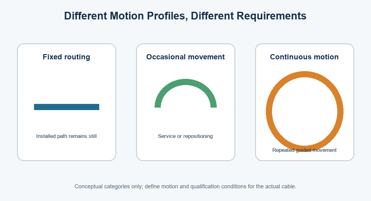
Motion categories are selection prompts, not performance ratings; qualify the exact cable against the machine profile.
Also check the transition from cable to connector. Repeated bending concentrated at the termination can damage conductors even when the cable body is suitable for motion. A strain-relief boot, clamp, routing guide, or overmolded cable assembly may help manage that interface when its material and geometry fit the design. It does not replace checking the cable’s permitted bend radius or assembly-level motion.
Electrical and Environmental Parameters to Confirm
Specify each conductor’s function, nominal cross-section or AWG size, strand construction if controlled, insulation type, color or identification, and electrical load. Confirm voltage, current profile, temperature rise, allowable voltage drop, protective-device coordination, and grounding requirements with the equipment design owner. Do not choose conductor size from a cable name or a current table alone; installation, bundling, ambient temperature, duty cycle, and terminations matter.
Select insulation and jacket materials for the actual environment. Consider temperature range, oil, coolant, cleaning agents, UV exposure, moisture, abrasion, flame or smoke requirements, and chemical compatibility. Cable properties such as temperature rating or oil resistance must be tied to the exact product and applicable test or listing. UL cautions through its product-designation guidance that markings identify intended uses and construction details; confirm the cable’s certification and permitted installation method for the target market.
For noisy installations, specify the source and frequency context where known, the sensitive signal type, shield construction, and how shield continuity or grounding should be implemented. “Shielded” alone is incomplete: grounding at one or both ends is an equipment-level decision influenced by system architecture, safety, and EMC requirements. For project-specific shielded builds, see OUKETECH’s custom shielded cable assembly information.
| Parameter | RFQ information to provide | Why it matters |
|---|---|---|
| Circuit definition | Conductor count, function, pinout, wire size, color code | Prevents circuit, polarity, and loading ambiguity |
| Electrical limits | Voltage, current profile, signal type, temperature rise, voltage-drop limit | Determines conductor, insulation, separation, and test choices |
| Movement | Static, occasional, flexing, torsion, or drag-chain; radius, speed, travel, cycles | Distinguishes installation flexibility from dynamic-life requirements |
| Environment | Temperature, chemicals, moisture, UV, abrasion, vibration, fire requirements | Drives insulation, jacket, shielding, and protective-layer selection |
| Mechanical envelope | Finished diameter, routing space, bend zones, clamp points, length tolerance | Confirms fit and avoids overconstraint or localized strain |
| Interface | Connector series and part number, contacts, backshell, seal, strain relief | Ensures mating compatibility and assembly feasibility |
| Verification | Continuity, shorts, insulation resistance, dielectric test, flex validation, records | Establishes measurable acceptance criteria for the build |
Fixed, Occasional-Flex, and Continuous-Motion Applications
Cable for fixed routing is selected primarily around electrical and environmental requirements, installation bend radius, and service access. Occasional-flex designs must tolerate expected repositioning or service movement. Continuous-motion cable requires a documented dynamic profile and suitable construction. The categories describe different demands; one should not be substituted for another solely because both use stranded conductors.
Common uses include control panels, industrial equipment, robotics, instrumentation, appliances, and mobile machinery. The same machine can contain multiple cable types: stationary trunk wiring, moving-axis cables, sensor leads, and power connections may each require distinct constructions. OUKETECH describes its robotics cable assembly support for custom projects; confirm any cycle-life or torsion claims against the exact offered product and approved test conditions before specification.
Assembly and Verification Considerations
The assembly drawing should control cut length, strip length, pin assignment, connector orientation, branch geometry, shield termination, labels, and acceptance criteria. Crimp tooling and contacts must match the wire and connector specifications. Soldering, splicing, potting, overmolding, or sleeving should be defined where used. A correct bulk cable can still become a defective assembly through a wrong pinout, damaged insulation, poor strain relief, or shield discontinuity.
At minimum, define a visual and electrical acceptance plan. Continuity and short-circuit checks can verify intended electrical paths and detect unintended connections; they do not prove dynamic flex life, insulation endurance, shielding effectiveness, or field reliability. Additional dielectric withstand, insulation resistance, pull-force, dimensional, functional, environmental, or flex testing should be selected for the project and executed against approved limits. OUKETECH’s custom cable assembly workflow describes build-to-print, inspection, and project-defined test planning; request only the tests needed by the design and acceptance plan.
| Potential defect | Possible cause | Useful control or verification |
|---|---|---|
| Intermittent open during movement | Conductor fatigue, tight bend, restraint, or termination stress | Reproduce the motion profile; inspect routing and strain relief; define dynamic validation |
| Wrong circuit or polarity | Pinout or color-code interpretation error | Controlled wiring table, connector view orientation, and circuit-level continuity test |
| Short circuit | Stripped strands, damaged insulation, contamination, or incorrect termination | Visual inspection plus short-circuit testing under the approved plan |
| Shield discontinuity | Incorrect drain or braid termination, poor clamp contact, or drawing ambiguity | Specify shield map and termination; inspect and test according to system requirements |
| Jacket cracking or swelling | Incompatible chemical, temperature, UV, or bend condition | Confirm material compatibility and environment; validate with representative exposure |
| Connector pullout or conductor break at exit | Inadequate retention or concentrated bend load | Confirm strain-relief design and required mechanical pull or motion validation |
Cost and Lead-Time Drivers
Price depends on more than cable length. Conductor count and size, copper content, insulation and jacket materials, shielding, special flex construction, connector choice, termination labor, overmolding, tooling, test requirements, documentation, order quantity, and component availability all influence quotation. A cable with extra conductors or a robust shield can increase diameter and assembly work, while a custom hybrid design may reduce installation labor elsewhere. Compare the complete system cost and validated use case.
Lead time is also sensitive to connector availability, custom cable minimums, material qualification, tooling, sample approval, and testing. Early technical completeness reduces clarification cycles. If an alternate connector or material is proposed, require written approval and confirm electrical, mechanical, environmental, regulatory, and service implications before release.
Buyer Checklist: What to Send With an RFQ
Send a drawing or representative sample with a BOM and connector part numbers. Include the conductor schedule, pinout, cable length and tolerance, motion profile, environment, shielding and grounding concept, labeling, packaging, quantity forecast, and required test records. Mark unknowns clearly for engineering review rather than allowing assumptions to become production requirements.
Before approving a sample, check that the actual cable manufacturer and part number match the specification; verify jacket markings, connector keying, pin assignment, dimensions, bend routing, shield termination, and strain relief. Confirm which inspections and test reports are included in the quotation. For repeating programs, control drawing revisions, substitutions, and approval records so later orders use the validated configuration.
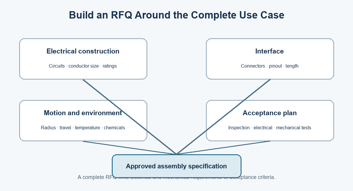
A complete RFQ connects electrical and mechanical requirements to inspection and acceptance criteria.
How OUKETECH Can Support a Multi-Conductor Cable Project
OUKETECH’s current custom cable assembly page describes manufacturing to customer drawings, BOMs, pinouts, samples, and test requirements, with project support from prototypes through production. Related options include control cable assemblies and shielded cable assemblies. Suitability, materials, motion qualification, certification, and test scope must be confirmed for the specific design before order release.
For a useful review, provide the cable specification, conductor schedule, connector series and part numbers, pinout, required length, motion and environmental profile, annual volume, and acceptance criteria. Contact OUKETECH to request a drawing review and project quotation.
FAQ: Frequently Asked Questions
What is a flexible multi conductor cable?
It is a cable with two or more insulated conductors and a construction intended to bend within defined limits. The term does not by itself define its bend radius, flex life, voltage rating, or suitability for continuous motion.
Is a stranded multi conductor cable suitable for a drag chain?
Not automatically. Stranding can support flexibility, but drag-chain suitability depends on the complete cable construction and the machine’s motion, radius, speed, temperature, and life requirements. Confirm qualification for the intended profile.
What is the difference between flexible cable and continuous-flex cable?
Flexible cable may be intended to bend during installation or occasional service. Continuous-flex cable is designed and tested for repeated motion under specified conditions. Obtain the exact test setup and limits behind any cycle-life statement.
Do I need shielding?
Shielding may help manage electromagnetic coupling when the signal, noise source, and equipment layout call for it. Define shield construction and termination strategy with the system designer; a shield alone does not guarantee noise-free operation.
Can power and signal conductors share one multi-core cable?
Sometimes, if the circuit separation, insulation, noise coupling, temperature rise, and applicable product approvals meet the design requirements. The equipment engineer should approve the construction and test plan.
Which information helps a supplier quote accurately?
Provide the conductor schedule, electrical ratings, cable construction, connector part numbers, pinout, length tolerance, motion profile, environment, quantity, and required testing or documentation. Drawings and samples help resolve interface details.