

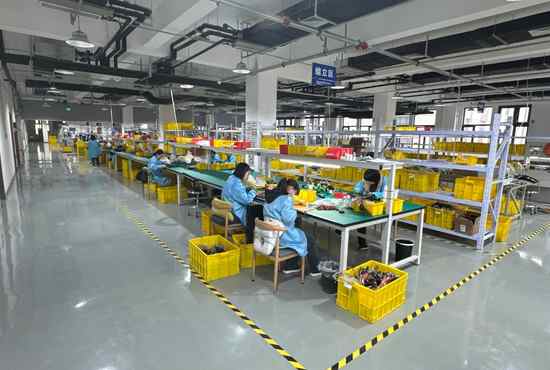
An electrical cable is an insulated conductor or group of conductors assembled to carry electrical power, signals, or data. Cable selection depends on more than conductor material: voltage and current, insulation, shielding, flexibility, installation method, exposure, connectors, and applicable product and installation standards all matter. This guide explains the main cable types and the information engineers and buyers should confirm before specifying one.
What Is an Electrical Cable?
An electrical cable is a manufactured interconnect made from one or more conductors with insulation and, depending on the design, additional layers such as a shield, filler, binder, or outer jacket. The construction protects the conductors and helps the cable perform in its intended electrical, mechanical, and environmental conditions. A cable’s name alone does not establish its rating or suitability; check the actual datasheet and markings.
In everyday usage, “wire” may refer to a single conductor, while “cable” often refers to one or more insulated conductors grouped into a construction. Terminology differs between industries and product standards, so a purchase specification should identify the required construction and rating rather than rely only on the word wire or cable.
Electrical cables can carry power, control signals, communications, radio-frequency (RF) signals, or data. A mains power cable, a flexible equipment lead, a shielded sensor cable, and an Ethernet cable all carry electrical signals, but they are not interchangeable. Their conductor geometry, insulation system, shielding, impedance, jacket, and qualification requirements differ.
Main Parts of an Electrical Cable
A cable is designed as a system of layers. Each layer serves a purpose, and removing or changing one can affect electrical performance, mechanical life, safety, and installation compatibility.
| Cable element | Main function | Specification questions |
|---|---|---|
| Conductor | Carries current or a signal | Copper or aluminum? Solid or stranded? What size, strand construction, and resistance limit? |
| Insulation | Separates conductors electrically | What voltage and temperature rating, dielectric properties, and material are required? |
| Pairing or laying | Controls circuit relationship and handling | Are conductors twisted, paired, cabled, or arranged in a flat ribbon? |
| Shield | Reduces coupling from or to electromagnetic interference | Is foil, braid, drain wire, or a combined shield required, and how will it be terminated? |
| Filler or binder | Maintains shape and organizes cores | Does the construction need a round profile, stable lay, or specified core count? |
| Outer jacket or sheath | Protects the cable from its surroundings | What abrasion, oil, moisture, UV, chemical, flame, and flex exposures apply? |
Conductors: Copper, Aluminum, Solid, or Stranded
Copper is common in power, control, and signal cables because it combines good conductivity with broad availability and established termination options. Aluminum is used in some power-distribution applications where its lower density and system economics are useful. Aluminum usually needs a larger conductor cross-section than copper for comparable electrical performance, and the cable and terminals must be designed for the intended application. Material choice alone does not determine ampacity or system suitability.
A solid conductor is one continuous metal element. Stranded conductors use multiple smaller wires, which can improve flexibility and resistance to repeated movement when the strand construction is suited to the application. Stranding does not automatically make a cable suitable for continuous flexing; conductor strand class, bend radius, cable construction, routing, and cycle requirements still need review.
Conductor size may be stated in American Wire Gauge (AWG), circular mils, or square millimeters. These systems are not labels for interchangeable cable performance. The correct size depends on load, allowable voltage drop, temperature limits, installation conditions, protection, and relevant code or product requirements.
Insulation, Shielding, and Jacket
Insulation surrounds each conductor and provides electrical separation. Common polymer families include PVC, polyethylene (PE), cross-linked polyethylene (XLPE), fluoropolymers such as PTFE, and elastomers such as silicone or rubber. They have different thermal, dielectric, chemical, flexibility, and processing characteristics. Avoid choosing by material name alone: specific compound, thickness, construction, listing, and rated conditions govern the result.
A shield is a conductive layer intended to manage electromagnetic interference (EMI) or radio-frequency interference (RFI). Foil, braid, served wire, and combinations are used in different constructions. Shielding performance depends on frequency, coverage, transfer impedance, grounding, connector termination, and cable routing. Adding a shield does not guarantee noise immunity if the full system is not designed and installed accordingly.
The outer jacket is the cable’s environmental and mechanical covering. A jacket may be selected for abrasion, oils, moisture, sunlight, chemicals, flame behavior, low-temperature flexibility, or repeated movement. “Outdoor,” “oil-resistant,” “flame-retardant,” and similar descriptions should be supported by the cable’s product rating and the intended installation requirements.
Common Types of Electrical Cable
Electrical cables are most usefully grouped by construction and function. A type name narrows the search, but the applicable specification still determines whether a product can be used in a particular installation.
| Cable type | Typical construction or role | Common selection focus |
|---|---|---|
| Single-conductor wire | One insulated conductor, often used in equipment or wiring systems | Voltage, conductor size, insulation rating, enclosure or raceway, termination |
| Multi-conductor cable | Several insulated conductors under a common sheath | Core count, circuit assignment, overall diameter, jacket, bend and routing needs |
| Control cable | Multiple conductors for control, instrumentation, or machine circuits | Signal type, pair or core identification, shielding, noise environment, flex |
| Coaxial cable | Center conductor, dielectric, and concentric outer conductor/shield | Characteristic impedance, frequency, attenuation, shielding, connector interface |
| Twisted-pair cable | Two conductors twisted together, often repeated across pairs | Pair construction, impedance, crosstalk, data rate or signal protocol, shielding |
| Flat or ribbon cable | Parallel conductors in a flat profile | Pitch, conductor count, termination method, bend direction and space |
| Flexible cord or cable | Construction intended for movement or portable equipment, subject to its rating | Flex duty, strain relief, abrasion, temperature, voltage and applicable standard |
| Power cable | Construction intended to distribute electrical power | Voltage class, conductor size, insulation system, installation and accessories |
A control cable may carry low-level sensor signals or control power, while a power cable is selected for a power circuit. A coaxial cable is a transmission line with a defined impedance, not simply a shielded power cable. A data cable’s category or protocol performance depends on the complete design and installation. These distinctions matter when replacing a cable or combining multiple functions in one assembly.
How to Choose the Right Electrical Cable
Start with the circuit and installation rather than a generic cable category. Documenting the application first helps engineers and purchasing teams avoid a nominally similar cable that fails on voltage, temperature, movement, environment, or approval requirements.
1. Define the Electrical Requirements
Record nominal and maximum voltage, continuous and peak current, conductor count, signal type, frequency or data protocol, and any allowable voltage drop or signal loss. For power cables, a conductor size table is only a reference: the actual current rating depends on cable construction and installation conditions, and final sizing must follow the applicable code and manufacturer data.
For high-voltage power systems, cable selection also covers insulation level, accessories, earthing, fault conditions, and system configuration. IEC 60183 provides guidance on selecting certain extruded-insulation high-voltage AC cable systems above 1 kV; IEC 60502-1 covers construction, dimensions, and tests for specified 1 kV and 3 kV power cables. These standards have defined scopes and should not be treated as universal cable-selection rules.
2. Match the Environment and Movement
Specify the actual conditions: indoor or outdoor installation, ambient temperature, moisture, sunlight, oil or chemical exposure, abrasion, vibration, washdown, and expected flexing. Include whether the cable is fixed, moved occasionally, flexed repeatedly, or used in a drag chain. Ask the cable supplier for the applicable bend radius and flex-life evidence for the exact construction where motion is important.
A cable that works inside a protected enclosure may not survive exposure to sunlight, coolant, repeated bending, or mechanical impact. If the cable will pass through an opening or connect to moving equipment, consider strain relief, abrasion protection, connector sealing, and routing as parts of the same design decision.
3. Select Conductor and Construction
Choose conductor metal, size, strand construction, core count, pair arrangement, and shielding based on the electrical and mechanical requirements. For shielded circuits, define how the shield will be grounded and terminated. For signal or communications circuits, specify impedance, pair balance, attenuation, and protocol requirements where relevant. For a custom interconnect with connectors or branches, document pinout, length, and interface details as well as cable data.
4. Verify Ratings, Standards, and Approvals
Confirm the cable’s rated voltage, temperature, environmental properties, flame or smoke characteristics when required, and applicable product markings. Distinguish the cable product standard from the electrical installation code and from customer-specific acceptance criteria. A component’s certification does not by itself approve every system-level use or installation method.
For example, IEC 60502-1 has a specific scope for extruded-insulation power cables in fixed installations at stated voltage ratings. It does not cover every flexible cord, control cable, communications cable, or equipment harness. In North America, consult the cable listing and the adopted installation code for the jurisdiction and application. The UL Wire and Cable Marking and Application Guide is a useful reference for understanding product markings and use categories; the actual product certification and local requirements still need confirmation.
5. Confirm Terminations and Installation Constraints
Cable performance can be limited by its terminations. Confirm conductor compatibility with terminals, connector contact size, strip length, crimp or solder requirements, sealing, cable entry diameter, bend space, and strain relief. Check installation constraints such as conduit fill, routing clearances, support, pull tension, separation from noise sources, and access for maintenance.
For equipment OEMs, specify the complete interconnect where cable is supplied with connectorization, branches, labels, or protective components. OUKETECH’s custom cable assembly manufacturing and custom wire harness manufacturing pages describe build-to-print routes for those assemblies. A bare cable specification and a finished assembly specification answer different procurement questions.
Cable, Cable Assembly, and Wire Harness: How Are They Different?
A cable is the conductor construction itself. A cable assembly adds specified terminations, such as connectors or contacts, and may include overmolding, sealing, labels, or strain relief. A wire harness organizes and protects one or more wires or cables into a routed set, often with branches and multiple termination points. Terminology varies by company, so define the supplied item by drawing, bill of materials, pinout, and acceptance requirements.
| Item | What is being specified? | Typical buyer document |
|---|---|---|
| Cable | Conductor, insulation, core arrangement, shielding, jacket, ratings | Cable datasheet or cable specification |
| Cable assembly | Cable plus connectors/terminations and assembly features | Assembly drawing, connector list, pinout, test requirements |
| Wire harness | Routed interconnect with branches, identification and protective components as specified | Harness drawing, BOM, formboard or routing data, acceptance criteria |
For a more detailed comparison, see OUKETECH’s cable assembly guide and its cable assembly vs. wire harness selection guide.
Electrical Cable Specification Checklist
Before requesting a quote or approving a substitute, provide the information that controls fit, function, installation, and acceptance:
- Application and installation location
- Voltage, current, frequency or data protocol, and circuit function
- Conductor material, size, strand construction, and number of cores or pairs
- Insulation, shield, drain wire, filler, and jacket requirements
- Length, routing, branch dimensions, and minimum bend radius where applicable
- Temperature, moisture, UV, chemicals, abrasion, vibration, and movement conditions
- Required product standard, listing, marking, and customer approval
- Connector, terminal, pinout, sealing, and strain-relief details for assemblies
- Testing, inspection, labeling, packaging, and documentation requirements
- Annual volume, order quantity, prototype needs, and revision control
If a requirement is not known, mark it for engineering review rather than substituting a guessed value. This is especially important for ampacity, high-voltage insulation, flame performance, continuous flexing, and hazardous or regulated installations.
FAQ
What is the difference between electrical wire and electrical cable?
Wire commonly refers to one conductor, while cable commonly describes one or more conductors combined with insulation and sometimes additional protective layers. Product and industry terminology varies. Specify construction, ratings, and intended use to remove ambiguity.
How do I select an electrical cable type?
There is no universal choice. Select by circuit function, voltage and current, installation environment, movement, routing, terminations, required approvals, and applicable installation rules. A cable suitable for fixed power wiring may not suit a moving control signal or high-frequency data link.
Is a shielded cable always better?
No. Shielding can help control EMI or RFI when selected and terminated for the system, but it adds cost, diameter, stiffness, and grounding considerations. The noise source, signal, frequency range, connector, and installation determine whether shielding is useful.
Can I replace a cable with one that has the same conductor size?
Not based on conductor size alone. Compare voltage and temperature ratings, insulation and jacket, conductor material, strand construction, number of cores, product approvals, connector compatibility, and installation conditions. A qualified designer should review substitutions that affect a regulated or safety-critical installation.
What details should I send for a custom cable assembly quote?
Provide a drawing or sample, cable and connector part numbers, pinout, dimensions, operating environment, target quantity, required tests, and any product approvals or documentation. OUKETECH’s contact page provides the inquiry route for a project review.
Plan the Cable Around the Application
The right electrical cable is the one whose conductor, insulation, construction, ratings, terminations, and installation conditions match the complete application. A product label or broad type name is only a starting point. For an OEM interconnect that needs connectors, branching, protection, or controlled repeat production, send OUKETECH the drawing, BOM, pinout, cable specification, quantity, and acceptance requirements for review.