

XT60 and XT90 connectors are two-position DC power connectors commonly used on battery leads, model equipment, robotics, and other compact power systems. Their differences include body size, contact geometry, cable compatibility, and the ratings published for each manufacturer’s exact variant. A connector marked “XT60” should not automatically be treated as suitable for 60 amperes, nor “XT90” as suitable for 90 amperes. Select from the actual product specification and validate the entire power path.
This comparison focuses on the connector family and the battery wire assembly around it. It does not approve a design for a particular battery, charger, vehicle, drone, or energy-storage system. Voltage, fault current, protective devices, operating temperature, enclosure, applicable product standards, and the consequences of failure still govern the final design.
The short answer: choose by the complete electrical and mechanical design
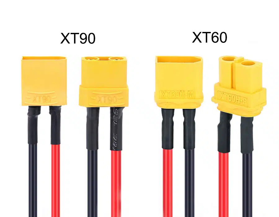
XT60 is usually the more compact interface, while XT90 variants have a larger body and may offer different contact and cable configurations. That physical distinction can affect packaging, handling, and routing. It does not, by itself, establish a safe operating current. For any design, check the connector’s exact manufacturer and suffix, its published test conditions, the wire and termination, and the system’s real current profile.
If the system already has an approved XT60 or XT90 interface, compatibility and qualification usually outweigh a theoretical upgrade. A larger connector may require more space, a different wire size, revised strain relief, new mating parts, and fresh system validation. A small connector can be adequate when the complete assembly is properly rated and tested. Neither outcome can be determined from the family name alone.
XT60 and XT90 comparison at a glance
| Design factor | XT60 family | XT90 family | What the design team should verify |
|---|---|---|---|
| Typical physical envelope | More compact two-pole body | Larger two-pole body | Exact drawing, mating envelope, clearance, and rear-cover dimensions |
| Cable interface | Variant-specific solder cup, board, or other construction | Variant-specific solder cup, board, or other construction | Approved suffix, conductor range, strip length, and assembly method |
| Current capability | Varies by manufacturer and part number | Varies by manufacturer and part number | Continuous and peak profile, test wire, temperature rise, and duty cycle |
| Voltage capability | Variant-specific | Variant-specific | Rated DC voltage, transients, insulation, and system protection |
| Installation space | Often easier in tight packaging | Needs more space for body and cable exit | Bend radius, access for mating, service access, and enclosure wall thickness |
| Current path | Contact plus wire and termination | Contact plus wire and termination | Resistance, joint quality, wire heating, and voltage drop under load |
| Special versions | Multiple housings and installation forms exist | H, S, board-mount, and other variants exist | Do not assume suffix functions are interchangeable; check manufacturer literature |
| Selection method | Verify the full assembly against application requirements | Verify the full assembly against application requirements | Approve a controlled bill of materials and test plan |
The table compares families rather than guaranteeing common specifications. “XT60” and “XT90” naming appears across product offerings and variants. Buyers should match the maker, complete part number, revision, and drawing before approving a substitute.
What the manufacturer ratings actually say
Current figures vary across connector variants and data sheets. For example, AMASS’s current XT60-F product page lists a 35 A current rating with 12 AWG wire under a stated temperature-rise condition of Δ≤85 K. Its XT90H-M page lists 45 A with 10 AWG wire under the same style of condition. Those figures are examples for those specific product pages, not universal ratings for every XT60 or XT90 product. The maker also lists different voltage, contact resistance, temperature, and mechanical-life details for each item. AMASS XT60-F specifications and AMASS XT90H-M specifications
This is why a generic chart can mislead. Product generations, cable terminations, housing variations, test wire, temperature-rise criteria, and manufacturer practices can all differ. A current rating measured under one test setup does not directly predict temperature in a closed battery compartment, under repeated acceleration, or beside another heat source. Use the specified test conditions to understand what the published value means, then validate the product in its intended use.
| Specification item | Why it matters | Review question |
|---|---|---|
| Rated current and test wire | A current value may depend on conductor gauge and test conditions | Was the rating established with the same wire size and termination planned for production? |
| Temperature-rise criterion | A connector’s temperature rise depends on current, contact resistance, and heat dissipation | What ambient temperature and allowable rise apply in the actual enclosure? |
| Rated voltage | DC switching and insulation stresses depend on voltage and circuit design | Does the exact variant’s voltage specification cover the maximum system voltage and transients? |
| Contact resistance | Resistance creates heat at the interface as current flows | Is the value specified for the selected part, and how will assembly variation be controlled? |
| Mechanical mating life | Frequent connection and disconnection can wear contact surfaces | How many service cycles are expected, and is the connector intended for routine servicing? |
| Environmental limits | Temperature, moisture, dust, chemicals, and vibration affect performance | Does the product have the required environmental protection, and is it installed as tested? |
When an XT60 may be the better fit
An XT60 option can be attractive when packaging is tight, the mating interface already exists, and the exact assembly meets the electrical requirements. Smaller housings can simplify access in compact equipment and leave more room for neighboring cables. They can also reduce the amount of enclosure space allocated to a disconnect point. These are mechanical advantages, not evidence of a particular ampacity.
Evaluate wire routing as carefully as the front-facing connector size. A compact connector attached to a stiff, large-diameter conductor may need more space behind the housing than its outline suggests. The cable exit direction, minimum bend radius, heat-shrink or protective boot, strain relief, and service access all affect the installed envelope. Check these details in the real enclosure or a representative mechanical model.
XT60 is not automatically the cost-effective choice if the wire must be downsized, the contact runs hot, or the design needs a frequent disconnect. Likewise, a change to XT90 does not fix excessive voltage drop, an undersized conductor, a poor solder joint, or an inadequate fuse. Diagnose the limiting element before changing the connector family.
When an XT90 may be the better fit
An XT90 variant may suit a design that needs a larger body or a different connector configuration and has room for it. Designers may favor a larger housing for physical handling or when an approved product line offers the required contact, wire, or accessory option. Confirm these requirements in the selected manufacturer’s documentation rather than inferring them from “90” in the model name.
The larger envelope brings trade-offs. It may interfere with adjacent components, increase cable bend pressure, complicate access behind a panel, or force a heavier, less flexible lead. The mating part must also be changed as a compatible pair. If a connector is keyed or polarized, preserve the intended polarity across the battery, charger, controller, and service equipment. Document the interface and inspect the first article before releasing a revised harness.
Some XT90-family variants are marketed with anti-spark features. That feature belongs to a particular variant and implementation; it is not an assumed property of every XT90 product. Confirm the manufacturer description, use instructions, mating procedure, and ratings. An anti-spark contact does not replace pre-charge design, overcurrent protection, safe service procedure, or system-level validation when those are required by the equipment.
XT90S and anti-spark selection
An XT90S-style connector is intended to reduce arcing during connection in certain capacitive-load applications. AMASS describes its XT90S as an anti-spark connector, but its product specifications still belong to the exact variant. The exact mechanism and required mating sequence depend on the manufacturer’s design. Do not treat the suffix “S” as a universal standard or assume that any connector labeled XT90S has identical construction. Verify the exact item, compatible mate, and instructions from the original maker. AMASS XT90S product information
Anti-spark features can reduce contact damage in an appropriate use case, but they do not make live connection safe in every application. Battery systems can deliver high fault energy. A shorted lead, reversed polarity, underspecified wire, or damaged insulation can cause serious equipment damage or fire. A disconnect should be used only within its electrical ratings and service conditions, with the system de-energized when the operating procedure requires it.
Current rating is not the current rating of the whole lead
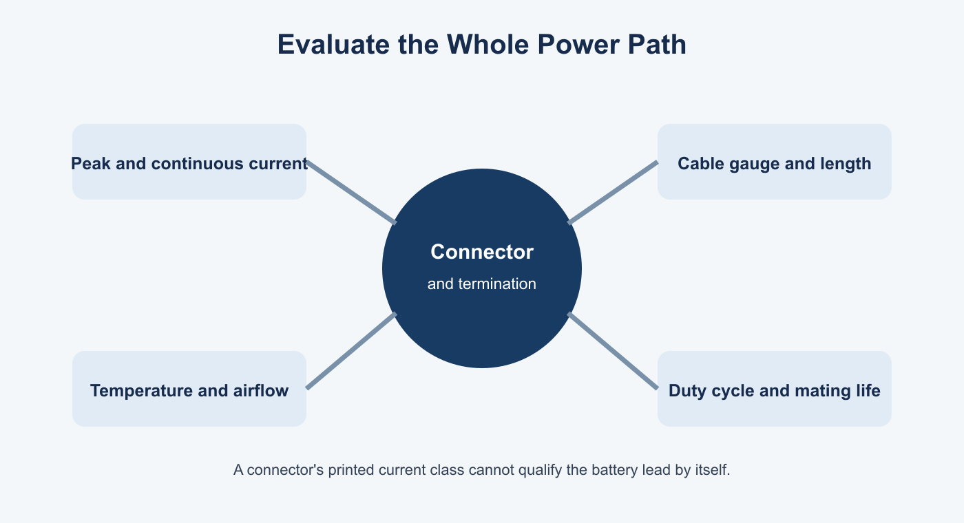
The connector is only one part of the circuit. Battery leads include conductors, terminations, insulation, splices, protective components, and mating contacts. The assembly can be limited by any of them. Wire size must account for current, conductor material, run length, allowable voltage drop, insulation temperature rating, bundling, ambient temperature, and cooling. A connector’s published number does not make an undersized cable acceptable.
Peak current and continuous current also describe different operating conditions. A motor controller may draw brief startup or acceleration peaks, then operate at a lower average current. Battery discharge, repeated bursts, high ambient heat, or a long cable can still raise conductor and contact temperatures. Design the measurement or calculation around the real duty cycle. Record how long peaks last and how often they repeat, rather than using only an average value.
For a first-order check, resistive heating rises with current squared: doubling current through the same resistance produces four times the heat. This relation explains why a modest change in load can create a large thermal penalty at a resistive joint. It does not provide a connector qualification by itself; contact resistance changes with design, wear, assembly quality, and operating conditions. A test under representative conditions is necessary when the consequences or uncertainty warrant it.
How to select between XT60 and XT90
Use a documented selection process instead of starting from a connector name. First define the electrical and mechanical requirements. Then find a specific connector part number whose manufacturer documentation covers the intended use. Finally, review the attached wire and termination and confirm the assembly in the equipment.
| Step | Action | Evidence to record |
|---|---|---|
| 1. Define the load | Record nominal, peak, transient, and continuous current; voltage; duty cycle; and fault protection | System specification, load profile, and fuse or protection design |
| 2. Define the environment | Record ambient and local temperatures, enclosure, airflow, moisture, vibration, and chemical exposure | Application conditions and applicable environmental requirements |
| 3. Identify the exact connector | Record manufacturer, complete male and female part numbers, suffix, revision, and source | Approved datasheet and controlled BOM |
| 4. Match the cable | Select conductor gauge, material, insulation, length, and flexibility for load and routing | Cable specification and voltage-drop or thermal analysis |
| 5. Control termination | Follow the connector maker’s approved preparation and soldering or termination method | Work instruction, sample approval, and workmanship criteria |
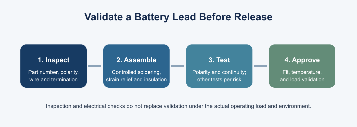
| 6. Verify the build | Check polarity, fit, contact retention, cable support, and electrical continuity | First-article inspection and agreed test record |
| 7. Validate in use | Measure temperature and voltage drop under representative loading and cooling | Test setup, instrument details, load profile, limits, and results |
The final decision may be an XT60, an XT90, another connector family, or a different architecture entirely. If the product is sealed, safety critical, used by consumers, or exposed to severe vibration, approvals and regulatory requirements may narrow the options. The selection belongs in the product’s controlled design records. Procurement should not substitute a visually similar part without engineering review.
Assembly and inspection points for battery leads
Solder-termination connectors need process control because the joint quality depends on conductor preparation, heat, solder wetting, and strain relief. Follow the selected product’s assembly instructions. Avoid excessive heating that damages the housing or insulation. Confirm that solder flows through the intended joint without bridging contacts, leaving loose strands, or creating a rigid unsupported section at the cable exit. A pull or bend check should follow the approved work instruction and should not be improvised as an unqualified acceptance test.
Polarity deserves a separate verification step. A connector’s housing may prevent some incorrect mating, but it does not ensure that both ends of a harness are wired consistently. Mark the positive and negative conductors in the drawing and the production documentation. Check the finished lead with a meter or fixture before connecting it to a battery or controller. Confirm pin orientation from the manufacturer’s drawing, since an image viewed from the mating face can differ from the wire-entry view.
Depending on the design and customer requirements, inspection may include part-number and revision checks, visual workmanship, dimensions, wire identification, polarity, continuity, short-circuit screening, and retention. Additional tests such as insulation resistance, dielectric withstand, or temperature rise should be selected according to the approved specification and test plan. The voltage and method must be suitable for the circuit and connected components. A test should not be added casually if it could damage electronics or exceed a component’s rating.
Common specification mistakes
| Mistake | Why it creates risk | Better practice |
|---|---|---|
| Treating the name as an amp rating | Product ratings are variant and test dependent | Use the exact manufacturer’s datasheet and documented test conditions |
| Comparing one manufacturer’s XT60 to another’s XT90 | Construction and qualification may not be equivalent | Compare specified values and mating compatibility from approved sources |
| Choosing wire gauge from connector family | Cable heating and voltage drop depend on length and installation | Specify conductor and insulation for the whole operating condition |
| Ignoring peak duration | Short peaks can still create repeated heating | Define amplitude, duration, frequency, and cooldown interval |
| Leaving polarity implicit | A reversed power lead can damage batteries or electronics | Show polarity on drawings and test finished assemblies |
| Assuming anti-spark means safe to hot-plug | Features and application limits vary | Follow the exact manufacturer’s instructions and system safety procedure |
| Substituting an equivalent-looking part without approval | Mating fit does not prove material, rating, or lifecycle equivalence | Require documented engineering approval and first-article validation |
| Testing only for continuity | Continuity cannot confirm thermal performance or current capacity | Select tests that correspond to the actual design risks |
What to send a supplier for a battery connector lead
A supplier can quote more accurately when the request identifies the controlled interface and conditions. Send a drawing or sample, connector part numbers, cable construction, finished length, conductor gauge, color, polarity, label requirements, annual and initial quantities, and any packaging instructions. Include the expected current profile, voltage, ambient temperature, enclosure conditions, mechanical movement, and testing or inspection expectations.
If an alternative connector is acceptable, define how equivalence will be assessed and who approves it. Specify whether a sample or first article is required before production. For recurring demand, include drawing revision control, change notification expectations, traceability needs, and the records required with each shipment. These details reduce quote assumptions and prevent an unapproved substitution from entering production.
OUKETECH’s battery wire harness manufacturing service describes build-to-print battery assemblies and project-specific connector, wire, routing, and test requirements. Its custom cable assembly service can review connector and termination details as part of the assembly specification. Send drawings, BOMs, or sample information through the OUKETECH contact page to discuss a project review. Product choice and qualification remain tied to the customer’s approved requirements.
FAQ
Is an XT90 automatically rated for 90 amps?
No. XT90 is a family name, not a universal current rating. The exact connector maker, part number, wire size, test condition, and installation determine which published specification applies. Verify the original product datasheet and qualify the assembly for its actual operating conditions.
Is XT90 always better than XT60?
No. XT90 has a larger physical envelope, but a larger connector is not automatically the correct choice. Fit, compatibility, rated performance, mating parts, cable requirements, service procedure, and validation determine suitability. If an existing interface is already qualified, changing it can create redesign and requalification work.
Can XT60 and XT90 connectors mate with each other?
No. They are different physical families and are not directly interchangeable. Use a properly designed adapter only if the electrical, mechanical, and safety requirements allow it, and ensure every interface in the adapter is correctly rated and protected.
Does XT90S eliminate arcing?
An anti-spark variant is designed to reduce connection arcing under specified conditions, but the effect and procedure depend on the specific manufacturer’s design. It does not remove all electrical, thermal, or service hazards and should not be treated as approval for unrestricted live connection.
Can an XT60 connector carry more current if I use thicker wire?
Thicker wire can reduce conductor resistance, but it does not increase the connector’s own contact rating or prove acceptable temperature rise. It can also be incompatible with the solder cups or housing. Use the connector maker’s wire guidance and validate the complete assembly.
What is the most reliable way to compare two connector options?
Compare exact part numbers using manufacturer drawings and specifications. Review current and voltage conditions, wire size, temperature rise, contact resistance, mating life, environmental limits, installation space, and assembly method. Then test a representative assembly under the expected load and environment where required by the design risk.