

An Automotive Wiring Harness Assembly needs more than correct wire colors and connectors. Every build must match the released drawing, bill of materials (BOM), pinout, materials, dimensions, and test plan. Small process mistakes can create an open circuit, a backed-out terminal, a weak crimp, damaged insulation, or a branch that will not fit the vehicle.
This guide explains the precautions buyers and production teams should define before and during assembly. It covers document control, incoming parts, wire preparation, crimping, connector loading, routing, testing, and supplier records. Acceptance limits must come from the customer specification and the component maker's application data. There is no single crimp height, pull force, test voltage, or inspection frequency that fits every automotive harness.
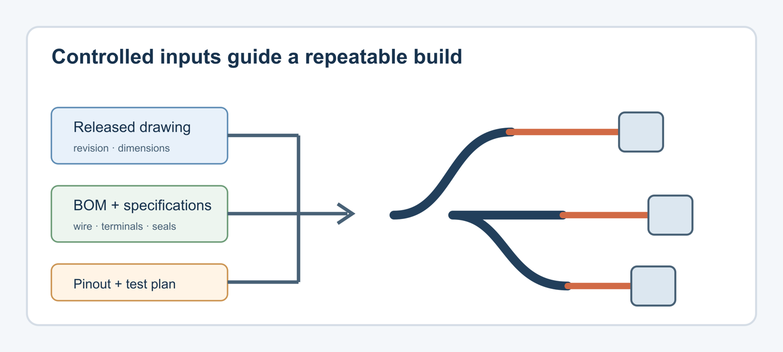
Conceptual vector illustration. It does not show an actual OUKETECH product or facility.
What Should Be Confirmed Before Automotive Wiring Harness Assembly?
Before production starts, the buyer and supplier should agree on one current build package. It should connect every physical part and operation to a revision-controlled requirement. A sample or photograph can help explain shape and fit, but it cannot define hidden materials, cavity assignments, wire construction, tolerances, or test limits. Resolve conflicts before material is cut.
At minimum, release a drawing, BOM, pinout or connection table, wire specifications, connector and terminal part numbers, branch dimensions, protective materials, labels, test requirements, quantity, and delivery plan. Identify approved alternates and who can authorize a change. If the project is still at concept stage, label assumptions clearly and ask the supplier to list them in the quotation.
| Build input | Precaution | Risk when unclear |
|---|---|---|
| Drawing and revision | Show dimensions, datums, tolerances, branch direction, clips, and label zones | A supplier builds to an obsolete or interpreted layout |
| BOM | List manufacturer part numbers and approved alternates for wire, terminals, housings, seals, and protection | Similar-looking parts are substituted without approval |
| Pinout | Define each circuit from cavity to cavity and identify connector viewing direction | Mirrored views cause crossed or misplaced circuits |
| Environment | State mounting location and exposure to heat, vibration, fluids, water, abrasion, and flex | Material selection does not match the real installation |
| Inspection and test plan | Define methods, limits, sampling, records, and fixture coverage | Supplier and buyer disagree about what “tested” means |
| Volume and schedule | Separate prototype, launch, and recurring quantities | Tooling, material lead time, and production method are misquoted |
Use the same controlled information for quoting, prototype approval, and repeat orders. A revision block should identify released changes, while an assumption log should list open items. The buyer should approve each deviation in writing. A supplier should not change a terminal, wire, seal, or test method because a substitute is easier to buy.
For a more complete RFQ package, see OUKETECH's wire harness quotation information checklist. It helps buyers present drawings, circuit information, quantity, schedule, and packaging needs in a way a supplier can review.
Which Incoming Material Checks Prevent Assembly Errors?
Incoming inspection should confirm identity and condition before parts reach the work cell. Check labels and part numbers against the released BOM, then control lot or reel identity through the work order. A housing may look correct while its terminal, seal, plating, or keying differs. Material control protects the build from wrong-part and mixed-lot errors that visual final inspection may miss.
Define which characteristics receive full inspection, sampling, or supplier-document review. This decision should reflect part risk and the approved quality plan. Check wire type, gauge, color, insulation, and reel identification. Check terminals for the correct series, plating, and packaging. Check connector housings, seals, plugs, locks, clips, sleeves, and labels for the approved part number and damage.
Keep partial reels and opened component bags identified. Separate accepted, rejected, and unverified material. If a supplier proposes an alternate, ask for a documented comparison that covers fit, electrical rating, wire range, sealing, temperature, plating, and approval status. Do not accept “equivalent” as proof by itself.
How Can Teams Reduce Wire Cutting and Stripping Defects?
Wire preparation controls length and exposes the conductor for termination without damaging it. Use the wire type and process settings approved for the job. Confirm the reel, cut list, wire color, and machine recipe before a run, then check the first pieces. Inspect cut length, strip length, strand condition, exposed conductor, and insulation damage using the method in the work instruction.
Small defects at this stage can become hidden after bundling. A nicked strand can reduce conductor area. A long strip can leave bare conductor exposed. A short strip can prevent full conductor placement in the terminal barrel. A wire cut to the wrong length may pull on a connector or force an incorrect branch shape.
Use a clear measurement datum. State whether length is measured from wire end to wire end, terminal shoulder to terminal shoulder, or another drawing point. Control job changeovers so the previous wire or recipe cannot remain in the machine. For high-mix production, scan or independently verify the work order and wire identity when the risk warrants it.
What Are the Main Precautions for Automotive Harness Crimping?
A crimp is reliable only when the terminal, wire construction, and tooling form an approved combination. Confirm the terminal part number, wire size and strand type, applicator, press setup, and application specification before running parts. Check the first piece after setup and repeat the checks at the frequency required by the control plan. Do not use a generic crimp height or pull-force value.
Crimp checks may include conductor placement, strand capture, insulation support, bellmouth, cutoff tab, terminal deformation, crimp height or width, and pull force. The terminal manufacturer's application specification defines the relevant process window and measurement method. TE Connectivity explains that the crimp height tolerance for a contact should be taken from its application specification; its automotive power distribution guidance also illustrates the need to match the wire, terminal, and applicator.
Crimp height is useful process evidence, but one measurement cannot prove the complete connection. Pull testing answers a different question and can damage the sample. Visual inspection may identify a poor conductor brush or damaged terminal, but it cannot reveal every internal condition. Set the checks from the terminal data, customer requirements, and risk plan. Molex's Quality Crimp Handbook provides additional manufacturer guidance on crimp process evaluation.
| Crimp control | What it can show | Important limit |
|---|---|---|
| Setup and tooling verification | Correct terminal, applicator, wire, and machine recipe are used | Does not replace product inspection or validation |
| Visual inspection | Strand capture, insulation position, terminal damage, and visible crimp features | Internal defects may not be visible |
| Crimp-height measurement | Whether a measured crimp dimension is within the specified range | Limit is terminal- and wire-specific; it is not a complete performance test |
| Pull-force test | Mechanical retention under the defined sample method | Sample preparation and test speed affect the result; it does not prove sealing or vehicle durability |
| Cross-section review | Internal conductor compression and strand distribution on a prepared sample | Destructive, method-sensitive, and not a replacement for other controls |
Record the setup and results at startup, after tooling adjustment, and after material or applicator changes when required. Follow a controlled stop-and-contain process when results fall outside limits. Do not keep running parts while the team debates whether a defect is acceptable. Document the affected lot, disposition, rework approval, and restart check.
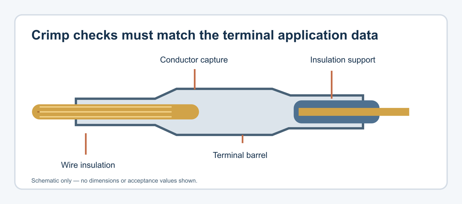
Schematic only. Actual crimp acceptance points and dimensions come from the terminal application specification and customer requirements.
How Should Connectors and Terminals Be Loaded?
Connector loading requires the correct cavity, orientation, seal, and retention feature. Read the cavity map from the defined connector view; never infer orientation from wire color alone. After insertion, use the connector maker's specified check for terminal seating and retention. Install secondary locks, cavity plugs, seals, backshells, and other parts in the approved sequence.
Common risks include a terminal inserted into a mirrored cavity, a contact that is not fully seated, a bent locking lance, a missing cavity plug, or a seal cut during insertion. A connector may mate at first and still fail after movement if the terminal is not retained. Use cavity identification and an independent check for high-risk circuits or complex pin maps.
Do not pull on wires in a way that can damage the terminal or seal. Where a retention check is required, define the method and acceptance criteria. Any terminal removal or repair should follow an approved procedure, because repeated extraction can damage the housing's locking feature.
What Routing and Protection Precautions Matter in the Vehicle?
Route the harness in the same controlled form used for dimensional inspection. A fixture or assembly board should locate branches, clips, and connectors without forcing the bundle into shape. Define measurement datums and whether dimensions include tape, sleeve, conduit, or protective covers. Check that branch lengths allow connector engagement, service access, and installation without sustained tension.
Protection must match the actual path. Abrasion, sharp edges, heat, chemicals, water, vibration, and repeated movement can affect different zones of the same harness. Specify where to use loom, braid, sleeve, tape, grommets, clips, strain relief, or shielding. Avoid extra covering that blocks inspection, hides labels, or changes a measured branch dimension.
Keep power, signal, and shielded circuits routed as the drawing and system design require. Define shield termination and drain-wire handling explicitly. Do not let the assembler choose a grounding method from a sample. Check that clips and ties do not crush insulation, bend conductors below their permitted radius, or create a tight bend at a connector exit.
Which Electrical Tests Should a Buyer Request?
The test plan should match the circuit and the failure risks. A point-to-point continuity and short-circuit test can identify many wrong-pin, open, or short conditions. It does not prove the harness will survive vibration, temperature, fluid exposure, or installation. Additional tests such as insulation resistance, dielectric withstand, contact resistance, functional checks, or environmental validation should be selected from the design and customer requirements.
Before release, review the fixture pin map, test limits, product connections, software or fixture revision, and result record. Challenge the fixture with known open, short, and miswire conditions using an approved validation method. A test report should identify the work order or lot and the applicable fixture or program revision when traceability is required.
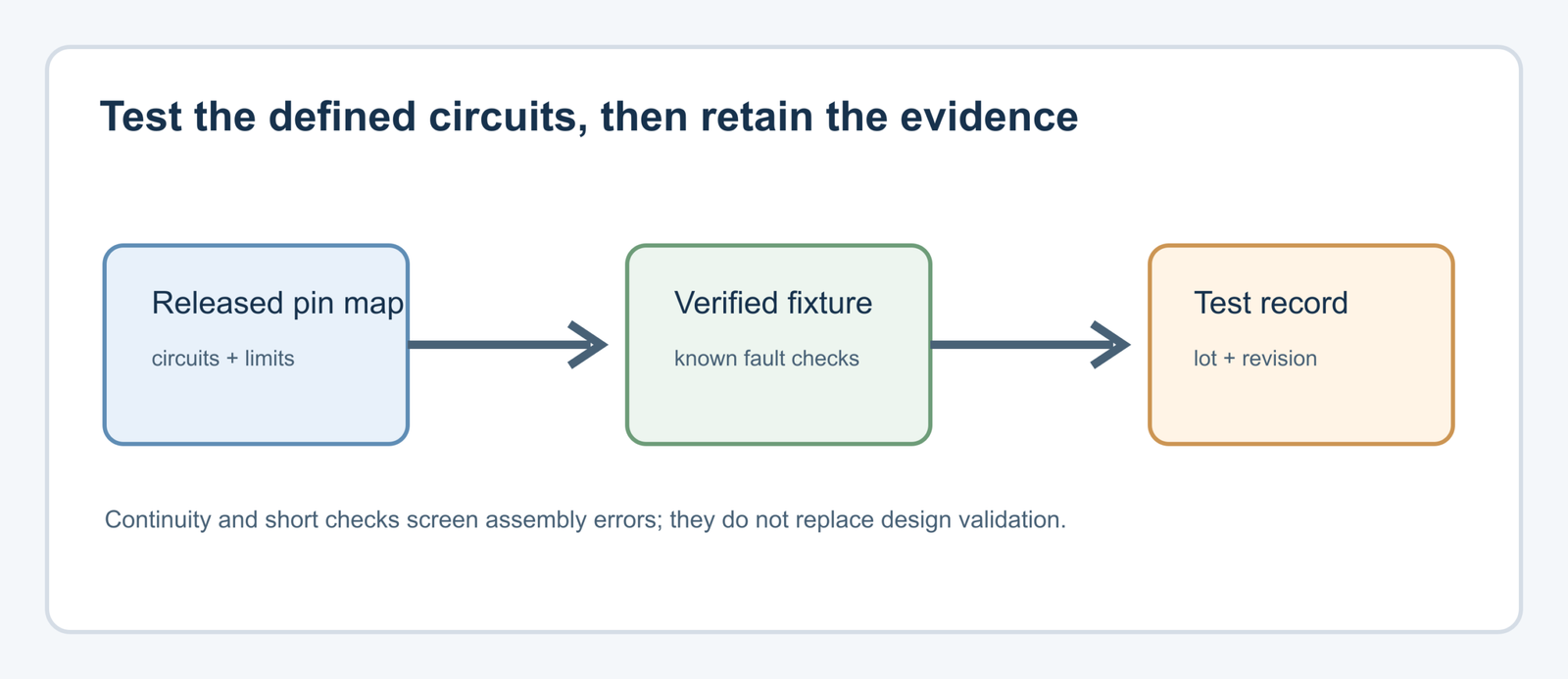
Conceptual test-planning diagram. Test scope depends on the approved customer plan.
Do not apply a generic high-potential (hi-pot) voltage to every harness. Test level and connection method must suit the insulation system, circuit voltage, connector, and attached electronics. A test intended for bare harnesses can damage components if the test setup is not designed for them. Separate design validation from routine production screening and state which party owns each activity.
How Can Buyers Evaluate Supplier Process Control?
Ask for evidence tied to your product and control plan. A certificate or capability statement does not show that the supplier uses the correct terminal applicator, checks every cavity, controls substitutions, or maintains the test fixture. Review representative records for material identity, setup approval, inspection, electrical test coverage, nonconformance handling, traceability, and change notification.
| Buyer question | Evidence to request | Why it matters |
|---|---|---|
| How do you control drawing and BOM revisions? | Released traveler, revision check, and open-item log | Prevents obsolete or assumed requirements |
| How do you approve a crimp setup? | Terminal-specific process data, setup record, and required measurements | Connects the tool setting to the actual wire and terminal |
| How do you prevent pinning errors? | Cavity map, loading instruction, and test-fixture coverage | Reduces miswire and terminal-location escapes |
| What does the electrical test cover? | Pin map, open/short detection, limits, and sample report | Defines what “100% tested” means for the quoted harness |
| How are material changes handled? | Alternate approval and customer-notification process | Prevents silent substitutions |
| What is traceable? | Example lot record linking material, work order, inspection, and test | Supports containment and root-cause work |
| How does the prototype transfer to production? | Process flow, tooling plan, first-article plan, and change log | Keeps hand-built samples from becoming an uncontrolled baseline |
If the customer requires Production Part Approval Process (PPAP), state the submission level, records, sample quantity, and approval owner in the purchasing documents. Do not assume the supplier's standard package matches the OEM's requirements. Confirm who owns validation, special-characteristic controls, change approval, and record retention before the launch date.
For a broad supplier and service overview, see OUKETECH's custom automotive wiring harness manufacturing page and automotive cable assembly sourcing guide. Use them alongside a product-specific audit and engineering review.
What Should an Automotive Wiring Harness RFQ Include?
An RFQ should let suppliers quote the same product and assumptions. Include the drawing, BOM, pinout, connector and terminal part numbers, wire details, branch dimensions, installation location, environmental conditions, quantity by phase, delivery schedule, required tests, packaging, and requested quality records. Ask suppliers to separate recurring unit costs from tooling, fixtures, validation, first articles, and PPAP work.
If information is incomplete, state what is known and what remains open. Request a list of assumptions and exclusions with the quotation. Compare the suppliers' proposed materials, test coverage, and documentation along with price and lead time. A lower initial unit quote can become more expensive if it excludes the required test fixture, approved components, or launch records.
For a practical handoff, provide: (1) a controlled product definition, (2) target prototype and production quantities, (3) use environment and vehicle location, (4) acceptance and validation requirements, and (5) the requested sample and launch dates. Ask for clarification where the drawing conflicts with the component application data. This step reduces avoidable rework after the purchase order.
Automotive Wiring Harness Assembly Precautions Checklist
Before approving a build or repeat order, confirm that:
- The drawing, BOM, pinout, and work instructions show the same current revision.
- Connector cavity view and pin numbering are unambiguous.
- Wire, terminal, connector, seal, and covering part numbers match the approved BOM.
- Alternates and deviations have written customer approval.
- Cut and strip settings are checked against the wire and terminal data.
- Crimp setup and inspection limits come from the applicable application specification.
- Connector seating, secondary locks, seals, and cavity plugs are verified.
- Branch geometry, protection, labels, and clip positions match the drawing.
- The test fixture covers the intended circuit map and is checked with known faults.
- Test limits do not risk attached components or exceed approved product requirements.
- Inspection, test, material, and change records are retained as agreed.
- Prototype process differences and production transfer are reviewed before release.
FAQ
What is a key precaution during automotive wiring harness assembly?
Control the released build information and make each process check traceable to a drawing, component specification, or customer requirement. Correct crimping cannot compensate for a wrong pinout, and a clear drawing cannot prevent a wrong terminal if incoming material is not controlled.
Is IPC/WHMA-A-620 enough to define all automotive harness requirements?
No. IPC describes materials, methods, tests, and acceptance criteria for cable and wire harness assemblies. The buyer should state the applicable revision and any customer-specific requirements. IPC notes that the standard does not define inspection frequency, so that frequency belongs in the agreed control plan. The IPC official pages currently show revision E in some locations, while the IPC China standards page lists revision F as the latest version; verify the contractually applicable edition before release.
Does a continuity test prove a harness is reliable?
No. Continuity and short tests screen electrical mapping and some assembly errors. They do not prove crimp quality, sealing, retention, vibration resistance, or environmental durability. Select validation and production tests for the harness design and the customer's requirements.
Can a supplier use a universal crimp height or pull-force limit?
No. Those limits depend on the terminal, wire construction, and application specification. The supplier should use the approved terminal data and customer criteria, then retain the measurements or records required by the control plan.
What files help a supplier quote an automotive wiring harness?
Send the released drawing, BOM, pinout, component part numbers, wire specifications, installation environment, quantity, schedule, testing requirements, packaging rules, and quality submission needs. A controlled sample can help explain fit, but it does not replace missing electrical or material requirements.
How OUKETECH Can Help
OUKETECH's automotive wiring harness service supports build-to-print automotive harness inquiries. For a project review, send the drawing or sample, BOM, pinout, connector and terminal part numbers, wire requirements, vehicle location, annual volume, test plan, and requested delivery schedule. OUKETECH can review the submitted information and identify questions that affect quotation or manufacturing planning. Confirm exact process scope, inspection records, standards, and delivery commitments in the formal quotation and technical proposal.
Engineering Sources
- IPC/WHMA-A-620 overview from IPC — standard scope and limitations, including inspection-frequency definition.
- IPC/WHMA-A-620 standards page from IPC China — lists revision F as the latest revision on the page, published May 20, 2026.
- TE Connectivity automotive power distribution guidance — manufacturer guidance on matching wire, terminal, applicator, and application-specific crimp dimensions.
- Molex Quality Crimp Handbook — manufacturer reference for crimp process evaluation.