

Extruded Cable vs. Molded Cable: What Is the Difference?
Extruded cable is made by continuously applying a polymer layer around a conductor or cable core through a die. “Molded cable” is less precise: it may refer to a cable body formed or encapsulated in a mold, or to a finished assembly whose connector-to-cable transition is overmolded. These terms describe different construction decisions, so buyers should identify the part being formed before comparing them.
In many assemblies, the cable itself has an extruded insulation and jacket while its connector end receives a separate molded boot. The useful comparison is therefore not always “extrusion or molding.” It is often continuous cable construction versus application-specific formed geometry at a termination or along a cable section. OUKETECH describes project-specific overmolded cable assemblies and custom cable assembly manufacturing as build-to-print services; the correct approach still depends on the released design and requirements.
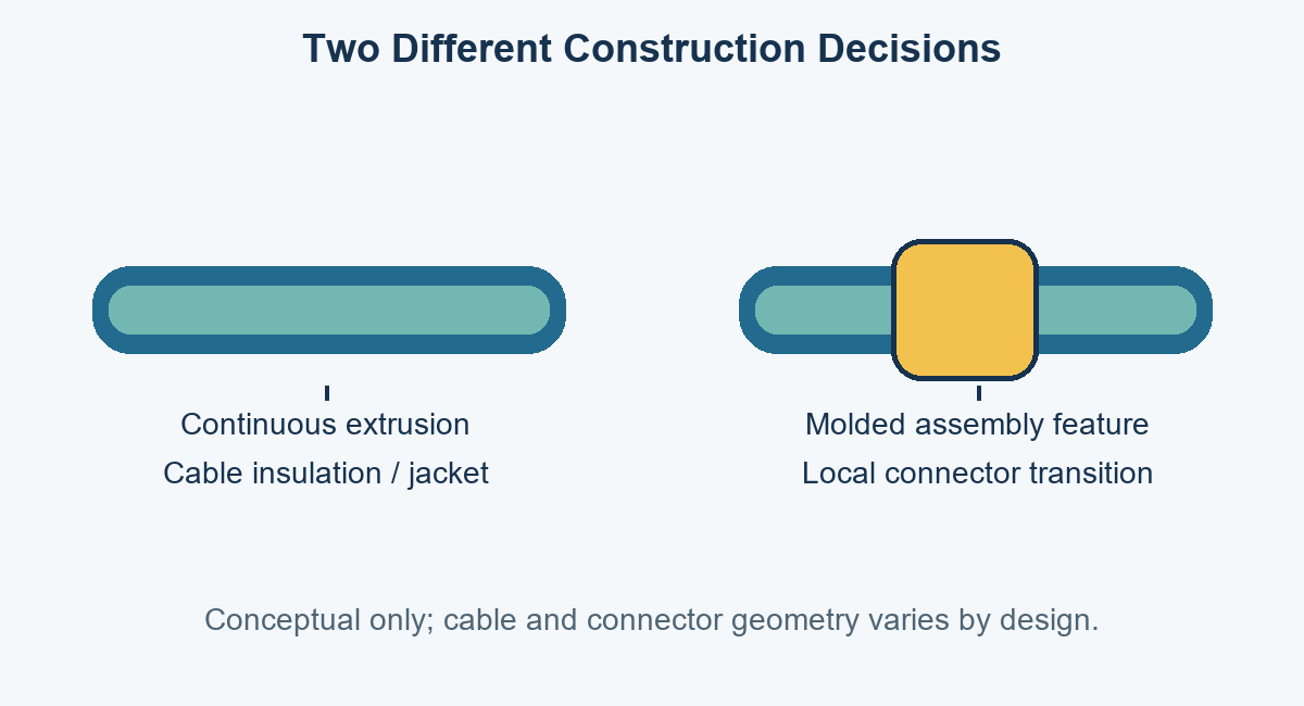
Conceptual process diagram only. It does not represent a specific factory process or product.
First Clarify What “Molded Cable” Means
Before requesting quotes, define whether the molded feature is the full cable body, a local protective section, or a connector overmold. A flat cable may use a molded or encapsulated body to hold conductors in a set arrangement. A connectorized cable may instead use standard extruded cable with a molded transition around the connector termination. These products solve different layout and protection needs.
| Term used in an RFQ | Likely meaning | What to confirm |
|---|---|---|
| Extruded cable | Insulation, sheath, or jacket applied continuously through a die | Cable construction, materials, dimensions, electrical and mechanical ratings |
| Molded cable | Ambiguous; may mean molded body, encapsulated conductors, or a molded assembly feature | Identify the molded zone and provide a drawing or reference sample |
| Overmolded cable assembly | Molded material added around a connector, termination, or cable transition | Geometry, material, bond or retention strategy, sealing target, and validation |
| Flat molded/encapsulated cable | Conductors held in a defined flat profile by a molded or laminated body | Pitch, conductor spacing, profile, bend zone, termination, and environmental limits |
The distinction matters because extrusion is generally a continuous production process, while molding uses a cavity to form a defined shape around a part or insert. The processes can coexist in one assembly. For example, an extruded cable jacket may enter a mold with a connector and termination so the final part has a shaped boot. The process name alone does not specify whether the interface is sealed, how much pull load it withstands, or how it behaves under repeated bending.
How Cable Extrusion and Molding Differ
Extrusion pushes or draws heated polymer through a shaped die around a moving wire or cable core. It is well suited to continuous lengths and repeatable cross-sections. Molding places an insert or material charge in a tool cavity and forms material around it, enabling local or three-dimensional geometry. Specific machine setups differ, so suppliers should confirm the proposed process for the design rather than relying on generic process labels.
| Design question | Extruded construction | Molded or overmolded construction |
|---|---|---|
| Typical use | Continuous insulation, sheath, or jacket along cable length | Local connector transition, boot, encapsulated section, or shaped body |
| Geometry | Primarily continuous cross-section and length | Cavity-defined three-dimensional geometry around inserts or conductors |
| Length/profile variation | Long lengths can be produced continuously; profile changes may require line or tooling changes | Shape can be tailored locally; mold design and setup are needed |
| Interface opportunity | Can create continuous layers in the cable structure | Can integrate a connector transition, strain-relief shape, or selected protective feature |
| Design variables | Die, material flow, core arrangement, wall dimensions, cooling, line controls | Cavity, gates/vents, material compatibility, insert position, shrinkage, release, and transition geometry |
| Cost drivers | Material, line setup, profile, run length, and process controls | Tooling, setup, material, cycle, part volume, and validation |
| Key verification | Dimensions, electrical insulation, jacket integrity, and specified cable tests | Fit, retention, dimensions, material/interface behavior, and project-specific environmental or mechanical tests |
These are process-level tendencies, not guarantees. A poorly designed extruded jacket can have defects, and a molded part can have voids, incomplete fill, weak bonding, or dimensional variation. Buyers should define measurable acceptance criteria and require evidence appropriate to the product risk.
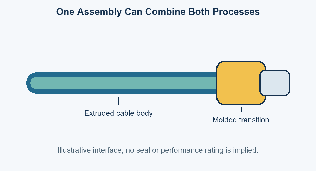
A single assembly can combine continuous cable layers with local molding at an interface; actual designs vary.
When Extruded Cable Is a Practical Choice
Extruded construction is commonly used when a project needs continuous insulated conductors, a consistent jacket profile, or a cable supplied in a specified length. It can be suitable for fixed routing and for dynamic applications when the complete cable construction is designed and qualified for the required motion. Extruded construction by itself does not establish bend radius, flex life, voltage rating, chemical resistance, or regulatory approval.
Choose a cable using the conductor size and stranding, insulation system, core lay, shield, fillers, jacket, diameter, temperature, and installation conditions. For motion, specify the bend radius, travel, speed, acceleration, torsion, cycle target, support arrangement, and temperature. Ask for the data sheet and qualification evidence for the exact part number. A cable marketed as flexible is not automatically suitable for a drag chain or repeated robot motion.
Extruded cable also offers design flexibility through material and layer choices, but compatibility and process windows must be confirmed. A particular jacket polymer may not bond reliably to an overmold compound without a compatible material pairing, surface preparation, mechanical retention, or other design measures. Treat any bond claim as design-specific and verify it in the proposed construction.
When Molded Features Add Value
A molded feature can add a custom exit angle, boot shape, connector transition, local protection, or controlled bend region where a standard backshell, clamp, or heat-shrink solution does not meet the product envelope. It can also consolidate selected parts. The practical benefit depends on geometry, materials, cable and connector compatibility, tooling, and qualification—not on the word “molded.”
Consider overmolding when the connector interface needs an integrated shape, handling protection, identification feature, or a defined transition. If the design has an ingress-protection target, specify the actual target and test method. An overmold does not automatically make a cable assembly waterproof: leakage paths can remain at the cable-jacket interface, connector mating face, insert, or parting line. Validate the complete assembly in its intended configuration.
Molding also introduces design commitments. Tooling must suit the connector and cable envelope, material must be compatible with inserts and service conditions, and molded dimensions need tolerances. Changes to connector position, exit angle, color, or outer profile may require tool changes or new qualification. The supplier should identify one-time tooling, sample and approval steps, minimum order assumptions, and ownership or storage terms in the quotation.
Performance Depends on the Complete Design
Cable performance comes from the full construction and its use conditions. A termination can fail from concentrated bending even when the cable body meets specification. A molded boot can shift the bend location rather than eliminate bending. Similarly, a continuous extrusion can protect conductors but cannot guarantee that a connector interface, splice, or cable exit will withstand a project’s pull, vibration, chemical exposure, or repeated motion.
Review these factors together:
- Electrical: conductor count and gauge, current and voltage, signal type, insulation, shield, grounding, and circuit separation.
- Mechanical: cable diameter, routing space, bend radius, pull, torsion, vibration, clamp locations, and strain-relief transition.
- Environment: temperature, fluids, cleaning agents, UV, abrasion, moisture, dust, and fire or smoke requirements.
- Interfaces: connector part numbers, keying, contact termination, backshell or overmold geometry, and mating conditions.
- Verification: continuity, shorts, insulation resistance, dielectric withstand, dimensional inspection, pull, flex, or ingress testing where required.
For electrically sensitive builds, OUKETECH’s custom shielded cable assembly page provides a relevant starting point for discussing shield layout and terminations. The shield path and grounding method still need to match the equipment architecture and approved drawing.
Cost, Tooling, and Lead-Time Trade-Offs
Extruded cable costs are affected by material, conductor content, layers, shield, profile, run length, production setup, and availability. Molded features add costs associated with tool design and manufacture, sample iterations, material compatibility checks, setup, and per-piece molding operations. At higher volumes, tooling may be spread over more units, but this does not prove that molding is the lowest-cost option for a specific program.
Compare the whole delivered assembly. A molded feature may reduce separate boots, clamps, or manual assembly steps, while a simpler cable termination may avoid dedicated tooling. Conversely, a custom molded design may reduce installation risk or consolidate parts in a space-constrained product. Request separate line items for non-recurring engineering, tooling, samples, production pieces, tests, and expected lead times. Confirm whether tooling is dedicated, who owns it, and what conditions apply to storage and maintenance.
| Cost or schedule factor | Extruded cable | Molded feature or assembly |
|---|---|---|
| Initial engineering | Core, material, profile, and cable specification review | Cable/connector fit, mold design, material/interface review, and DFM |
| Tooling | Die or line setup may apply for nonstandard profile | Dedicated mold tooling is commonly required for custom geometry |
| Production quantity | Often suited to continuous cable runs; minimums depend on supplier and construction | Per-part setup and tooling make quantity and repeat demand relevant |
| Revision impact | Material or profile changes may affect cable setup and qualification | Geometry or insert changes can require tool modification and revalidation |
| Schedule risks | Material availability, line scheduling, and cable minimums | Tool manufacture, sample iteration, material compatibility, and approval |
These are quotation questions, not universal cost rules. A supplier should explain assumptions for the exact design, including raw cable sourcing, tooling amortization, scrap, testing, and production quantity.
How to Specify the Right Construction
A quote request should let suppliers evaluate the actual use rather than infer it from a product label. Send a drawing or controlled sample, bill of materials (BOM), connector and contact part numbers, pinout, cable specification, overall dimensions, quantity forecast, and the intended operating environment. Mark unresolved details as open questions for engineering review.
For a molded part, show where the mold begins and ends, cable exit direction, critical external dimensions, connector orientation, draft or parting constraints if known, and the intended mechanical function. For a dynamic assembly, document how the cable moves and where it is supported. For a seal, define the required exposure and acceptance test; do not rely on “waterproof” as a sufficient specification.
| RFQ item | Information to provide | Why it matters |
|---|---|---|
| Cable body | Manufacturer and part number, conductor schedule, shield, jacket, diameter | Identifies the electrical and mechanical construction |
| Connector interface | Series and part number, contacts, keying, orientation, mating part | Prevents fit and termination ambiguity |
| Molded geometry | Drawing or model, exit angle, dimensions, color, features | Defines tool and inspection requirements |
| Use conditions | Temperature, chemicals, moisture, vibration, routing, motion | Drives material and validation choices |
| Quantities | Prototype, pilot, annual demand, order releases | Supports tooling and commercial assumptions |
| Acceptance | Dimensions, electrical checks, mechanical tests, records | Gives both sides measurable release criteria |
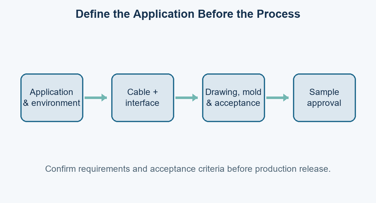
Use the approved drawing and acceptance plan to connect application needs to the production configuration.
Inspection and Validation Should Match the Risk
Inspection should verify the features that control function and assembly risk. A first sample can establish connector orientation, dimensions, pinout, cable exit, fit, and workmanship. Production controls may include visual inspection and electrical tests according to the approved plan. Testing should be selected for the failure mode: continuity does not prove pull strength, and a visual check does not demonstrate a sealing target or flex life.
For overmolded designs, define how to assess fill, flash, voids, interface condition, insert movement, critical dimensions, and cable-exit geometry. If bond strength or mechanical retention matters, set a method and acceptance limit for the specific materials and geometry. If repeated flex is part of service, validate with a representative fixture, motion profile, environment, and cycle criterion. Record deviations and approve the sample configuration before production release.
For extruded cable, verify the exact cable part and applicable product documentation. Relevant checks may include conductor continuity, insulation tests, dimensions, markings, or specified material and environmental evidence. A custom assembly can introduce additional risks at cut ends, splices, contacts, shields, or transitions, so inspect and test the finished build as well as purchased cable where the plan requires it.
Common Selection Mistakes
The most common mistake is treating “extruded” and “molded” as complete specifications. They are process descriptions, not performance ratings. Another error is assuming an overmold guarantees waterproofing or a longer life. Neither conclusion follows without defined interfaces and test evidence.
Avoid these shortcuts:
- Comparing different product scopes. Make sure the quote compares like for like: bulk cable, flat cable, connectorized assembly, or local overmold.
- Choosing from material names alone. Grade, formulation, wall thickness, geometry, and service conditions affect behavior.
- Using “flexible” without motion details. State static versus dynamic use, radius, speed, travel, torsion, and target cycles.
- Requesting a seal without a test. Specify exposure, assembled state, test method, and acceptance criteria.
- Skipping tool and revision terms. Confirm ownership, storage, maintenance, change costs, sample approvals, and affected qualification.
- Accepting unqualified performance statements. Ask for product-specific data and the test setup behind claims.
How OUKETECH Can Support an OEM Cable Assembly
OUKETECH’s custom cable assembly service describes build-to-print work from drawings, BOMs, pinouts, samples, and test requirements. Its overmolded cable assembly page is relevant when a design calls for a connector transition or shaped molded feature. Availability, material choices, tooling, test scope, and schedule should be confirmed against the specific project.
Send a released drawing or sample, BOM, connector part numbers, cable specification, application conditions, target quantities, and acceptance requirements. Include the intended job of any molded zone—such as routing, mechanical transition, or specified environmental protection—so the engineering review and quotation address a defined need. Contact OUKETECH to request a project review and quote.
FAQ: Frequently Asked Questions
Is an extruded cable better than a molded cable?
Neither process is inherently better. Extrusion commonly produces continuous cable layers, while molding creates a defined shape around a part or section. Choose based on construction, geometry, service conditions, quantity, tooling, and validated requirements.
Is an overmolded cable the same as a molded cable?
Not necessarily. “Molded cable” is ambiguous and can describe several constructions. An overmolded cable assembly specifically has molded material around a connector, termination, or cable transition; the cable body may still be conventionally extruded.
Does an overmold make a cable waterproof?
No. A molded exterior alone does not establish an ingress rating. The connector face, cable interface, parting line, and assembly design must all meet the target and pass the specified test in the intended configuration.
Does an overmold improve strain relief?
It can provide a designed transition or retention feature, but performance depends on geometry, materials, cable construction, and loading. Specify and validate the mechanical requirement; an overmold can also create a stress concentration if the transition is poorly designed.
Which process is cheaper?
There is no universal answer. Extrusion costs depend on cable materials, profile, setup, and run length; molding adds tooling and setup but may consolidate parts or assembly steps. Compare tooling, piece price, quantity, tests, and total system cost for the actual design.
What should I send for a molded cable assembly quote?
Provide a drawing or sample, BOM, cable and connector part numbers, pinout, molded-zone geometry, quantities, use environment, and acceptance criteria. Also identify tooling expectations and any required ingress, pull, flex, or electrical tests.