

Common JST connector types include compact wire-to-board families such as SH, GH, ZH, PH, and XH, as well as wire-to-wire families such as SM and RCY. Their pitches range from 1.0 mm to 3.96 mm, but pitch alone does not establish compatibility or suitability. A correct selection also depends on the exact series, housing and terminal part numbers, mating orientation, wire range, current, voltage, retention, and environmental requirements.
“JST” refers to Japan Solderless Terminal, the connector manufacturer. It is not one universal connector standard. In everyday repair and hobby discussions, the name is often used loosely for small crimp connectors, which can lead to mismatched parts. This guide compares commonly encountered JST families and explains what engineers and buyers should verify before specifying them.
Common JST Connector Types at a Glance
The table below is a family-level orientation guide, not a substitute for a manufacturer datasheet. Published electrical ratings vary by exact product configuration, including the terminal, wire size, number of energized circuits, header, and test conditions. Confirm the current JST specification for the exact part number before design release.
| Series | Nominal pitch | Common connection format | Typical design context |
|---|---|---|---|
| SH | 1.0 mm | Wire-to-board | Space-constrained electronics, compact internal signal wiring |
| GH | 1.25 mm | Wire-to-board | Dense equipment connections where a secure lock is useful |
| ZH | 1.5 mm | Wire-to-board | Compact internal connections in small electronics |
| PH | 2.0 mm | Wire-to-board | Battery, sensor, and general low-profile internal connections |
| PA | 2.0 mm | Wire-to-board | Applications using the PA positive-lock family and matching components |
| XH | 2.5 mm | Wire-to-board | General internal wiring where its specified header and housing are used |
| EH | 2.5 mm | Wire-to-board | Internal equipment wiring using EH-specific components |
| SM | 2.5 mm | Wire-to-wire | Detachable in-line connections, including some lighting and equipment wiring |
| RCY | 2.5 mm | Wire-to-wire, commonly 2 circuit | Compact in-line connections in product-specific designs |
| VH | 3.96 mm | Wire-to-board | Power supply and other circuits designed around the VH system |
JST SH: 1.0 mm Pitch for Compact Connections
The SH family is a small 1.0 mm pitch wire-to-board system. Its compact footprint can suit dense electronic assemblies where board area and connector height are limited. Applications may include small consumer devices, portable electronics, and compact control modules, provided the circuit load and mechanical conditions fit the selected SH parts.
The small contact size makes correct wire preparation and crimp tooling especially important. Confirm the contact part number, conductor and insulation ranges, PCB header style, and any retention feature specified for the exact assembly. Do not assume that every 1.0 mm connector found in a product is JST SH.
JST GH: 1.25 mm Pitch with a Secure Lock
JST GH is a 1.25 mm pitch wire-to-board family with a secure locking feature. JST positions it for high-density internal connections in electrical and electronic equipment. The positive latch can help maintain engagement where a compact connector needs deliberate retention, such as electronics modules, robotics, and selected unmanned-aircraft equipment.
The lock does not make GH suitable for every vibration or outdoor application. Verify the mating header and housing, cable routing and strain relief, temperature exposure, and the product’s actual electrical load. JST’s published GH specifications identify the applicable wire range and ratings for particular parts; use those values rather than a generic “1 amp” label copied across variants.
JST ZH: 1.5 mm Pitch for Small Equipment
The ZH family uses a 1.5 mm pitch in a compact wire-to-board format. It can be considered for internal signal or low-power wiring in products where a smaller connector is useful but the exact application does not call for a different locking system or larger interface.
Possible contexts include compact electronics, instrument modules, and small control boards. Treat these as application examples, not a blanket endorsement for a battery or power path. Current capacity must be established from the matching JST datasheet and the complete circuit design, including conductor size, temperature rise, duty cycle, and enclosure conditions.
JST PH: 2.0 mm Pitch for Compact Board Wiring
JST PH is a 2.0 mm pitch wire-to-board family used in many compact electronic assemblies. It is commonly encountered in battery leads, sensors, small appliances, and hobby electronics. Engineers often select it where a modest connector footprint and a removable board connection are useful.
PH is not interchangeable with PA simply because both families have a 2.0 mm pitch. Housing geometry, terminals, headers, and locking details are series-specific. Before substituting PH for another connector, check the mating interface, polarity, contact system, wire range, board footprint, and electrical ratings.
JST PA: 2.0 mm Pitch with a Different Locking System
JST PA also has a 2.0 mm pitch, but it is a distinct connector family with its own positive-lock construction and compatible components. It may appear in equipment designs that require the PA interface and retention characteristics. Do not describe it as a higher-current PH replacement without checking the actual component data and application requirements.
For a repair or redesign, match the series and part numbers rather than relying on a ruler measurement. A connector can appear to fit while having different contact geometry, retention, or electrical behavior. The approved mating parts and PCB land pattern should remain controlled in the bill of materials (BOM).
JST XH: 2.5 mm Pitch for General Wire-to-Board Connections
JST XH is a widely recognized 2.5 mm pitch wire-to-board family used in consumer electronics, equipment, and some hobby products. Its larger footprint than SH, GH, or PH can make assembly and handling more practical when board space allows. Example uses include internal signal and low-voltage power wiring, subject to the exact XH component ratings.
XH shares a nominal 2.5 mm pitch with EH and other connector families. The shared spacing does not make the housings or contacts compatible. Confirm the XH series marking or part number, mating header, contact, pin count, and wire specification before ordering replacements or building a cable.
JST EH: 2.5 mm Pitch for Equipment Wiring
The EH family is another 2.5 mm pitch wire-to-board system. It is used in electronic equipment and control assemblies designed for EH components. Although an EH connector may look similar to another 2.5 mm family, the mating interface and terminal design are series-specific.
If a product documentation set calls for EH, preserve that series in sourcing and production records. If the original part cannot be identified, compare manufacturer drawings and inspect the mating header instead of selecting by pitch or product photo alone.
JST SM: 2.5 mm Pitch for Wire-to-Wire Connections
JST SM is a wire-to-wire family intended to connect cable ends without a PCB header. This arrangement can simplify modular wiring, field replacement, or linking separate sections of an assembly. It is seen in some lighting products and other equipment with detachable in-line connections.
Wire-to-wire construction does not inherently mean outdoor-rated or waterproof. Check whether the specified assembly includes seals or other environmental protection; confirm polarity, wire range, retention, and the mating half. For installations subject to pulling or vibration, provide suitable cable support so the connector is not carrying harness loads.
JST RCY: Compact Two-Circuit Wire-to-Wire Connection
RCY is a compact wire-to-wire family commonly used as a two-circuit in-line connection. It may be found in small equipment or battery-related wiring where the original design specifies the RCY interface. The family’s small size should not be mistaken for a universal battery connector designation.
Battery applications require additional checks: polarity, maximum continuous and peak current, contact temperature rise, short-circuit protection, wire size, and strain relief. Identify both mating halves and their part numbers before specifying a replacement.
JST VH: 3.96 mm Pitch for Designed Power Connections
JST VH is a 3.96 mm pitch wire-to-board family used in power supply circuits and other equipment connections designed around the system. JST lists current ratings that depend on the applicable configuration; for example, its product information gives different conditions for standard and shrouded header types and different wire sizes. The often-repeated 10 A figure therefore must not be treated as a universal VH rating.
For power use, verify the exact terminal and header combination, conductor gauge, number of loaded circuits, ambient temperature, PCB layout, and derating requirements. A larger pitch or a positive lock does not by itself establish safe current capacity.
Wire-to-Board vs. Wire-to-Wire JST Connectors
Wire-to-board connectors join a cable to a PCB-mounted header. They are useful when a board needs a removable connection for assembly, service, or module replacement. SH, GH, ZH, PH, PA, XH, EH, and VH are commonly discussed in this context, although each family has its own component options and design constraints.
Wire-to-wire connectors join two cable ends. They can create an in-line disconnect without dedicating board area to a header. SM and RCY are examples encountered in this role. Select the connection format based on how the equipment is assembled and serviced, then verify the specific connector system and retention requirements.
| Design question | Wire-to-board approach | Wire-to-wire approach |
|---|---|---|
| What is the mating interface? | Crimp housing mates with a PCB header | One cable-side connector mates with another cable-side connector |
| What should be confirmed? | Header footprint, orientation, mounting, and housing clearance | Both mating halves, cable support, routing, and service access |
| Typical reason to use it | Removable PCB wiring | Detachable harness sections or in-line connections |
| Common risk | Wrong header orientation or footprint | Wrong mating half, polarity, or unsupported cable loads |
How to Identify a JST Connector Correctly
Start with the complete part number or controlled drawing. If those are unavailable, measure the center-to-center pitch of adjacent contacts, count circuits, inspect the housing and latch, and determine whether the connector mates to a PCB or another cable. These clues narrow the search, but only the series drawing or confirmed part number establishes the intended interface.
Use this identification sequence:
- Record any markings on the housing, cable label, BOM, or assembly drawing.
- Identify the mating component, including the PCB header or opposite cable connector.
- Measure pitch across several adjacent positions when possible to reduce measurement error.
- Count circuits and note keying, latch shape, housing height, and mating direction.
- Match the housing and contact part numbers to the manufacturer’s current documentation.
- Verify wire gauge, insulation outside diameter, crimp tooling, current, voltage, and operating environment.
Pitch is a useful screening measurement, not a compatibility test. In particular, families can share the same pitch while using different housings and terminals. Third-party parts described as “JST-compatible” may also differ from the genuine series in dimensions, retention, materials, or ratings. Validate a substitute against the approved mating part and the actual acceptance requirements.
How to Choose the Right JST Series
Choose the connector as part of the electrical and mechanical system. Begin with the required circuit count, current and voltage, wire size, PCB footprint or in-line arrangement, and available space. Then check the manufacturer specifications for the exact connector components and apply any design derating required by temperature, simultaneous loading, enclosure, and duty cycle.
Use this checklist before releasing a design or purchase order:
- Compatibility: Confirm the exact series and mating housing/header part numbers. Never approve a replacement based on pitch alone.
- Electrical load: Check current and voltage ratings for the selected terminals and header, along with wire size and loading conditions.
- Mechanical fit: Confirm circuit count, keying, orientation, board footprint, connector height, and clearance.
- Retention: Evaluate the series lock, cable strain relief, and expected vibration or handling.
- Environment: Check temperature, moisture, dust, chemicals, and any required sealing or material restrictions.
- Manufacturing: Confirm the terminal supports the selected conductor and insulation dimensions and that suitable crimp tooling and inspection criteria are defined.
- Supply control: Record approved manufacturer part numbers and any validated alternates in the BOM.
Common JST Selection Mistakes
The most frequent sourcing error is treating “JST connector” as a complete specification. The term identifies a manufacturer, while series and part numbers define the mating system. A second error is assuming connectors with the same pitch are interchangeable. XH and EH, or PH and PA, show why spacing alone is not enough.
Another risk is repeating a family-level current rating without its test conditions. A published value may assume a specific wire gauge, terminal, header, number of circuits, or temperature. The finished application may need derating. Do not choose a connector for a battery or power path until the complete circuit load and thermal conditions have been reviewed.
Finally, a connector that mates mechanically can still be wrong electrically or operationally. Reversed polarity, incorrect wire insertion, weak crimps, inadequate strain relief, or an unapproved substitute can cause overheating, intermittent operation, or equipment damage. Keep connector identity and wiring orientation visible in the drawing and inspection plan.
How OUKETECH Can Support a JST Cable Assembly
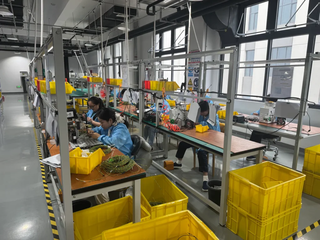
OUKETECH builds custom cable assemblies to customer drawings, BOMs, pinouts, samples, and project requirements. For a JST-based assembly, provide the exact manufacturer series and part numbers where available, mating interface, wire specification, circuit assignment, length and branch dimensions, expected quantity, operating environment, and inspection or test requirements. Engineering can review open specification points before quotation and production planning.
If you are developing a cable assembly around a JST connector, send OUKETECH your drawing, BOM, or sample for a project review. Include both mating part numbers and any approved alternate so the connector interface remains controlled from prototype through repeat production.
Frequently Asked Questions
What is the most common JST connector type?
There is no single answer across all industries. PH and XH are common in compact electronics and hobby products, while other applications use SH, GH, VH, or wire-to-wire families. Identify the connector by its series and part number, not by a general popularity claim.
Are JST connectors with the same pitch interchangeable?
No. Pitch only describes contact spacing. Families with the same pitch can have different housing shapes, terminal designs, latch geometry, and mating interfaces. Confirm the exact series and compatible part numbers.
What is the difference between JST PH and XH?
PH is a 2.0 mm pitch family, while XH is 2.5 mm pitch. Both are commonly used as wire-to-board connectors, but they have different mating parts and are not interchangeable. Check the manufacturer drawings and exact ratings for the selected components.
Is every 2.5 mm connector a JST XH?
No. EH, SM, RCY, and other connector families may also be described with a 2.5 mm pitch. Connection format and housing design differ, so measure pitch only as an initial identification step.
Which JST connector should I use for a battery?
Use the series specified by the equipment design or validate a new selection against polarity, continuous and peak current, wire gauge, temperature rise, retention, and protection requirements. “Battery connector” is not a sufficient specification, and family-level current numbers are not a substitute for checking the exact component datasheet.
What information should I send for a custom JST cable assembly?
Send the connector and terminal part numbers, mating connector details, drawing or pinout, wire type and gauge, cable lengths, circuit count, application conditions, quantity, and required inspections or tests. If the original part number is unknown, provide clear photos and the mating component for identification, then approve the final part before production.