

A custom utility trailer wiring harness gives trailer manufacturers control over circuit functions, branch lengths, connector interfaces, and environmental protection. A 4 pin harness generally serves basic lighting, while a 7 pin configuration can accommodate additional functions such as electric brakes, reverse lights, and auxiliary power. The correct design depends on the trailer’s electrical loads, tow-vehicle interface, installation layout, and operating conditions.
For OEM buyers, the purchasing question extends beyond choosing a plug. A repeatable harness specification must define how the assembly fits the frame, connects to lamps and brakes, resists damage, and passes inspection. Those details determine whether the harness arrives ready for installation or requires production-line modification.
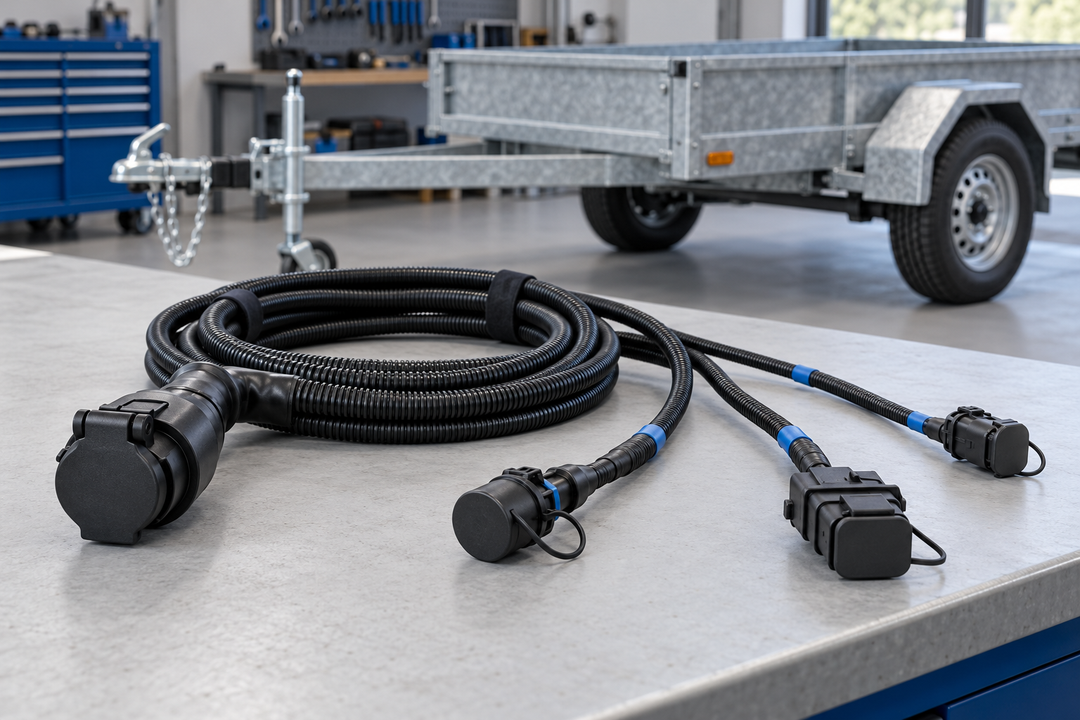
This guide focuses on trailer-side OEM harness procurement using common North American 4-way flat and 7-way RV blade applications. Other markets and connector families require their own interface definitions. The term “waterproof trailer wire harness” describes a design objective here; any specific protection claim requires defined assembly conditions and supporting validation.
What Makes a Custom Utility Trailer Wiring Harness Different?
A custom assembly follows the trailer’s electrical architecture and physical layout. Instead of adapting a universal kit during installation, the buyer defines trunk length, branch exits, terminations, mounting points, and identification before production. This approach is useful when repeated trailer builds require consistent fit, controlled variants, or documented electrical acceptance criteria.
For example, a landscape trailer may need rear combination lamps, side markers, and a tongue-mounted connection. An equipment trailer may add electric brake branches and an auxiliary feed. Both are utility trailers, but their harness requirements differ substantially.
Custom does not automatically mean a completely new connector or proprietary tooling. Standard approved components can be combined into a drawing-specific assembly. Reserve special molding or unique components for requirements that standard parts cannot satisfy.
Define the product boundary early. A trailer-side chassis harness differs from a vehicle-specific towing harness that connects to the tow vehicle’s lamps or electronics. Buyers searching for an OEM utility trailer wiring harness manufacturer should identify which side of the interface the supplier must deliver.
4 Pin vs 7 Pin Trailer Wiring Harness: Choose by Circuit Function
Choose the connector configuration from the required circuits and mating interface. In common North American applications, 4-way flat supports basic lighting and ground. A 7-way RV blade interface provides additional circuit positions. Pin count alone does not establish current capacity, sealing performance, or compatibility with another seven-position connector family.
| Selection factor | 4 pin / 4-way flat | 7 pin / 7-way RV blade |
|---|---|---|
| Typical circuit functions | Ground, tail/running lights, left turn/stop, right turn/stop | Basic lighting plus electric brakes, auxiliary power, and reverse functions in a common configuration |
| Typical procurement fit | Lighting-focused utility trailer programs | Trailer programs needing additional electrical functions |
| Drawing information required | Connector identity, circuit mapping, branch layout, lighting loads | Same information plus brake, auxiliary, and reverse-circuit requirements |
| Main specification risk | Assuming lamp compatibility or neglecting ground return | Confusing connector families, color conventions, or circuit ratings |
| Environmental protection | Determined by selected parts and assembly construction | Determined by selected parts and assembly construction |
These are common application patterns, not universal pin assignments. CURT describes the basic functions of a four-way connection in its 4-way connector guidance. Its seven-way harness example illustrates the additional brake, reverse, and power functions available in a suitable system. Neither source defines the specification for your custom trailer.
Custom 4 Pin Trailer Wiring Harness for Lighting Programs
A custom 4 pin trailer wiring harness can suit an unbraked utility trailer whose electrical requirements are limited to compatible lighting circuits. Specify each lamp branch, connector, ground connection, and mounting location. A left/right split can simplify routing when the chassis layout supports it.
Confirm whether the lamps use combined stop/turn signals or require another arrangement. Include side-marker and identification lamps where applicable to the trailer design. The harness supplier needs the complete load list, rather than a generic instruction to “wire the lights.”
Custom 7 Pin Trailer Wiring Harness for Brake and Auxiliary Circuits
A custom 7 pin trailer wiring harness is appropriate to evaluate when the trailer requires more than basic lighting. Identify the exact connector family and every cavity function. Seven-way RV blade and seven-pin round systems should never be treated as interchangeable based on contact count.
Electric brake wiring also requires compatible control equipment and a defined return path. An auxiliary feed needs its own load and protection review. A connector adapter cannot create a missing vehicle-side brake-control or power circuit; evaluate the complete vehicle-to-trailer system before approving the harness.
What Should “Waterproof Trailer Wire Harness” Mean in an RFQ?
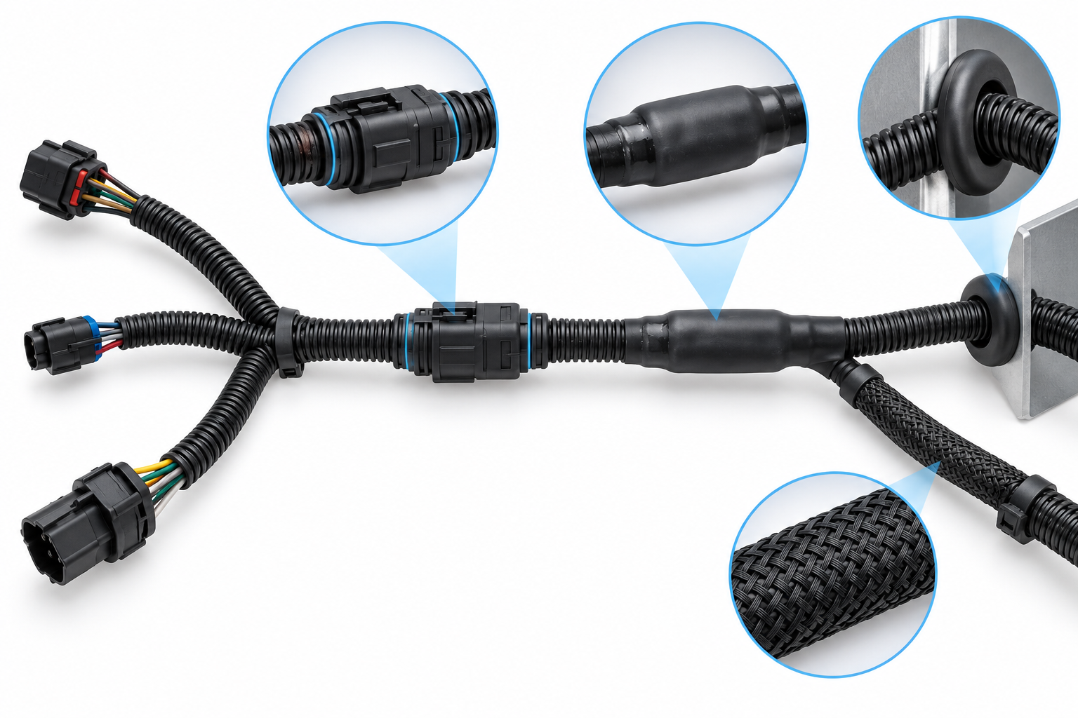
A waterproof requirement should identify the exposed locations, operating conditions, connector state, and acceptance test. Rain splash, temporary immersion, road salt, and pressure washing impose different demands. A sealed connector cannot establish the protection level of every splice, cable entry, lamp connection, or junction enclosure within the complete harness.
Avoid ordering only by an IP label. Ask which component or assembly carries the rating, which accessories are required, and whether the rating applies while mated, capped, or disconnected. TE Connectivity’s sealed connector guidance illustrates why protection can depend on backshell selection and installation conditions. That guidance does not establish a rating for an OUKETECH trailer harness.
| Exposure or failure risk | Design information to specify | Acceptance evidence to request |
|---|---|---|
| Water at connector interfaces | Connector and seal part numbers, wire insulation diameters, unused-cavity sealing, mating conditions | Approved component documentation and agreed assembly checks |
| Moisture entering splices | Splice location, sealing construction, materials, process limits | Approved splice samples and applicable environmental validation |
| Abrasion at frame openings | Grommets, sleeves, edge protection, clamp positions | Installed routing inspection on a representative chassis |
| Salt and corrosion | Exposure profile, contact materials, conductor choice, termination protection | Project-specific corrosion evaluation where required |
| Tongue movement and vibration | Flex zone, bend limits, strain relief, retention method | Fit review and agreed mechanical validation |
| Water at junction enclosures | Entry seals, mounting position, enclosure design and service access | Inspection and testing of the installed configuration |
A dust cap may help protect an unused connector without providing the same performance as a qualified mated interface. Split loom can organize wires and reduce abrasion exposure, but it is not a continuous water barrier. Overmolding also requires suitable materials and interface design; appearance alone does not prove sealing.
For boat-launch applications, record immersion frequency and fresh- or saltwater exposure separately. OUKETECH’s marine wiring harness resource provides a related starting point for discussing these environments. A boat trailer specification still needs to address its own plugs, lamps, splices, and installation conditions.
Custom Specifications That Control Fit and Electrical Performance
An OEM trailer harness drawing should connect the electrical requirements to the installed geometry. Define conductor construction, circuit loads, connector part numbers, branch dimensions, and protection details together. These choices interact: a larger wire can affect terminal compatibility, seal fit, bundle diameter, bend behavior, and the space needed at a frame opening.
Wire Size, Voltage Drop, and Ground Return
Choose wire size from circuit current, total path resistance, allowable voltage drop, installation temperature, bundling, and component ratings. Brake and auxiliary circuits may need different conductors from lighting branches. A single wire gauge selected from connector count is not a reliable design method.
Specify conductor material and cross-sectional requirements explicitly. Do not approve a substitution solely because two wires carry the same nominal gauge label. Review resistance, termination compatibility, and the application’s environmental requirements before accepting an alternative.
Ground deserves equal attention. If the design uses a chassis return, define the grounding points, fastening method, surface preparation, and corrosion protection. If it uses dedicated return conductors, include the shared current and complete return path in the electrical review. Continuity alone cannot establish acceptable voltage drop under load.
Branch Lengths, Routing, and Installation Tolerances
Specify dimensions from repeatable reference points such as connector faces, branch exits, or mounting features. State tolerances and the condition in which dimensions are measured. “Overall length” does not tell the supplier where the left lamp branch must reach.
Review movement at the tongue, tilt mechanisms, ramps, and suspension. Enough slack is needed for movement, but excessive slack can contact moving parts or road debris. Use an installed sample to check routing before approving recurring production.
Connectors, Splices, and Serviceability
List housing, terminal, seal, cavity plug, and accessory part numbers where applicable. Include the mating component or its controlled interface reference. Define pin numbering and whether the drawing shows the mating face or wire-entry face.
A trailer wiring harness with sealed connectors may also need replaceable lamp branches or accessible junctions. Modular construction can simplify repairs and product variants, although each added interface creates another connection to qualify. Compare service requirements with component cost and installation space before choosing the architecture.
OEM Applications: Match the Harness to the Trailer Program
The trailer application determines which design variables deserve priority. A general-purpose utility trailer, an equipment hauler, and a boat trailer can share connector formats while needing different routing, protection, and validation. Build a specification around actual exposure and loads instead of assuming that one “heavy duty” construction covers every program.
For landscape and general cargo trailers, focus on repeatable lighting branches, protected frame crossings, accessible lamp connections, and installation consistency. A custom trailer light wiring harness should be checked against the actual lamp locations and mounting hardware.
For equipment trailers, review brake branch routing, auxiliary loads, protected junction locations, and clearance around loading or tilt mechanisms. A 7 way trailer wiring harness for equipment trailers needs a circuit definition that covers the installed equipment and its control system.
For fleet or dealer programs, consider identification, packaging, and service documentation. Similar-looking variants can create installation errors if their labels and part numbers do not clearly distinguish them. Include drawing revision and approved configuration in the purchasing record.
How to Evaluate a Custom Trailer Wiring Harness Supplier
Evaluate the supplier against your drawing and acceptance plan. A useful quotation identifies included components, manufacturing assumptions, tooling, sample deliverables, and testing scope. Ask how the supplier controls pinning, branch dimensions, sealing details, and material substitutions. General statements about quality do not resolve these specific production risks.
| Control point | Failure it addresses | Evidence for buyer review |
|---|---|---|
| Drawing and bill-of-material review | Wrong connector, missing seal, ambiguous circuit | Approved drawing and resolved technical questions |
| Terminal application control | Damaged conductor or unsuitable crimp | Terminal-maker requirements and agreed inspection records |
| Pin-to-pin and short-circuit testing | Open, short, or wrong cavity assignment | Test coverage matched to the released netlist |
| Dimensional inspection | Branches unable to reach mounting locations | First-article dimensional results |
| Loaded circuit evaluation where required | Excessive voltage drop or unstable operation | Agreed load conditions and measured results |
| Environmental validation where required | Leakage, corrosion, or retention failure | Defined test configuration and acceptance criteria |
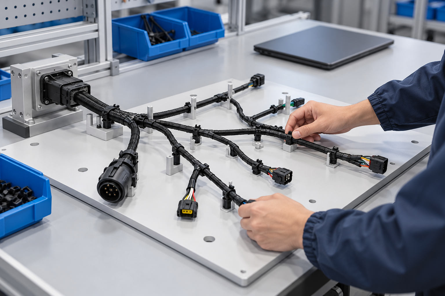
Distinguish routine production checks from qualification testing. A continuity test checks circuit connection; it does not prove waterproofing, corrosion resistance, or long-term flex performance. Environmental testing should specify sample configuration, exposure conditions, acceptance criteria, and responsibility for the work.
Request first-article approval before releasing a new configuration. A change to a seal, terminal, cable diameter, or branch location can affect fit and protection. Establish which substitutions require written approval and when a change triggers additional validation.
Cost, MOQ, and Lead Time for Custom Trailer Harness Orders
Custom harness cost depends on components, assembly work, tooling, test coverage, and order structure. More sealing features or additional branches can increase assembly and inspection effort. A lower unit price may exclude fixtures, qualification work, or packaging, so compare quotations against the same specification and deliverables.
Separate one-time development charges from recurring unit prices. Ask suppliers to identify special tooling, test fixtures, sample builds, and any minimum component purchase commitments. Standard connector availability may influence the schedule more than harness assembly time.
Prototype, pilot, and production orders also serve different purposes. A prototype checks design assumptions; a pilot build checks installation and production readiness. For purchasing context, see OUKETECH’s custom wire harness MOQ and lead-time guide. Confirm quantities and dates for your project rather than assuming a universal minimum order or delivery promise.
Avoid comparing quotations before resolving whether each supplier included the same conductor construction, mating parts, protection features, labels, and tests. Otherwise, the apparent saving may reflect a different assembly.
Request a Custom Utility Trailer Wiring Harness from OUKETECH
OUKETECH’s custom trailer wiring harness manufacturing service describes build-to-print support from drawings, bills of materials, pinouts, or approved samples, with prototype and production options. For a utility trailer program, use the quotation review to establish the required configuration, component availability, and acceptance scope before approving samples.
Prepare the following information for an RFQ:
- Trailer application, destination market, and trailer-side supply boundary.
- Required 4-way flat, 7-way RV blade, or other identified connector interface.
- Circuit table with cavity numbers, functions, loads, and ground-return arrangement.
- Harness drawing with trunk length, branch dimensions, tolerances, and mounting points.
- Wire specifications and connector, terminal, seal, and mating-part references.
- Water, salt, temperature, abrasion, movement, and storage exposure requirements.
- Sample quantity, expected order quantities, annual demand, and target schedule.
- Required inspections, test coverage, records, labeling, and packaging.
Use the custom wire harness quotation checklist to organize your files. Send the drawing and circuit requirements for review, and identify any unresolved items explicitly. This gives the supplier a practical basis for a quote and sample plan.
FAQ
Can a 4 pin trailer wiring harness operate electric brakes?
A common 4-way flat interface allocates its circuits to lighting and ground. It does not provide a dedicated electric-brake control circuit. Evaluate a suitable expanded interface and the compatible vehicle-side equipment when electric brakes are required.
Is every 7 pin trailer wiring harness waterproof?
No. Seven pins describe the contact count. Environmental protection depends on the connector family, seals, accessories, cable entries, splices, and assembly conditions. Request evidence for the specified configuration and exposure.
Can I order a custom-length trailer wiring harness with different lamp connectors?
Custom length and branch terminations can be included in an OEM specification. Provide the lamp connector references, mating interfaces, circuit assignments, and dimensions. Confirm component availability and manufacturing feasibility during quotation review.
Is wire color enough to approve a trailer harness pinout?
No. Use a controlled circuit table, connector cavity identification, drawing orientation, and electrical verification. Colors can assist identification but should not replace the released pinout.
What should I send for a waterproof trailer wiring harness quotation?
Send the drawing, circuit loads, component references, quantities, and exposure profile. Define whether protection is required while connected, capped, or disconnected, and identify the validation evidence needed for acceptance.