

A manufacturer of custom automotive cable assemblies must do more than terminate wires and install connectors. The supplier must translate a controlled drawing, bill of materials (BOM), pinout, environmental profile, and test plan into a repeatable build. Buyers should evaluate engineering review, crimp process control, inspection evidence, electrical testing, traceability, and change management before approving production.
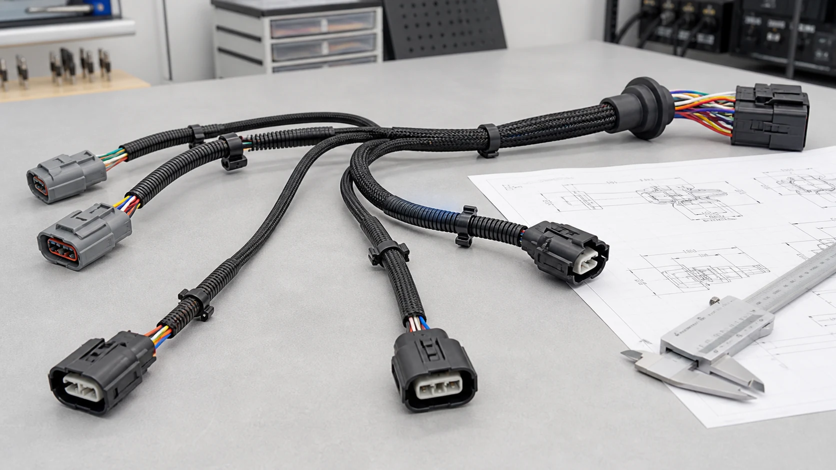
The phrase “automotive cable assembly” can describe a short sealed sensor lead, an overmolded camera cable, a battery interconnect, or a multi-branch harness. These products face different electrical, mechanical, thermal, chemical, and documentation requirements. A credible RFQ therefore starts with the vehicle location and circuit function, not a generic request for an “automotive-grade” cable.
What Does a Manufacturer of Custom Automotive Cable Assemblies Actually Provide?
Related OUKETECH resources: custom wire harness manufacturing.
A qualified manufacturer converts customer-controlled product requirements into inspected cable assemblies. The scope normally includes drawing review, component verification, tooling and work instructions, prototype or first-article builds, controlled termination and assembly, electrical inspection, packaging, and revision control. Design authority remains with the customer unless a separate design service is explicitly assigned.
Build-to-print manufacturing is a controlled translation process. The supplier must preserve wire identity, contact selection, cavity location, branch geometry, protective materials, labels, and test requirements across every accepted unit. If a drawing conflicts with a connector application specification or the physical mating environment, the manufacturer should stop and request clarification rather than silently improvise.
That distinction matters because a sample can appear correct while hiding serious production risks. A connector may mate on the bench but lack the required seal, terminal retention, polarization, or secondary lock. A cable may pass continuity yet fail after vibration because the conductor crimp, strain relief, bend radius, or clipping plan was not controlled.
The public IPC automotive and e-mobility resource identifies IPC/WHMA-A-620E as a relevant cable and wire harness assembly standard. IPC explains that the standard covers materials, methods, tests, and acceptability criteria for crimped, mechanically secured, and soldered interconnections. It does not replace the customer’s product drawing, terminal application specification, or vehicle-level validation plan.
What Information Should an OEM Send Before Requesting a Quote?
An actionable RFQ gives the manufacturer enough information to identify technical risk, material availability, tooling, inspection scope, and recurring cost. At minimum, send a revision-controlled drawing, BOM, pinout, connector and terminal part numbers, wire specifications, branch dimensions, annual volume, test requirements, and operating environment. Mark unresolved choices instead of hiding them.
| RFQ input | Why the manufacturer needs it | Common risk when missing |
|---|---|---|
| Drawing with revision and tolerances | Controls lengths, breakout locations, labels, coverings, and acceptance dimensions | Supplier quotes a visually similar but functionally different assembly |
| BOM with manufacturer part numbers | Confirms terminals, housings, seals, wire, clips, sleeves, and approved alternates | Unapproved substitutions or incorrect mating interfaces |
| Pinout or circuit table | Maps each conductor from cavity to cavity and defines splices | Wrong pinning, crossed circuits, or incomplete test coverage |
| Electrical requirements | Defines voltage, current, shielding, impedance, resistance, and isolation needs | Inadequate conductor size, shielding, or test method |
| Mechanical and environmental profile | Identifies temperature, vibration, abrasion, fluid, ingress, and flex requirements | Premature insulation, seal, clip, or strain-relief failure |
| Volume and launch schedule | Drives automation, tooling, capacity planning, and material commitments | Prototype process cannot scale economically or reliably |
| Inspection and submission plan | Defines first article, capability evidence, PPAP, reports, and retention | Disagreement about evidence after parts are built |
| Packaging and labeling rules | Prevents connector damage, branch deformation, and identification errors | Good parts arrive damaged or cannot be received correctly |
Provide native drawings when possible, plus a controlled PDF for quoting. Include mating connector information and the available package space. If the assembly must follow an existing sample, identify which sample characteristics are authoritative and which require engineering confirmation. A physical sample alone rarely defines conductor material, plating, internal seals, allowable tolerances, or validation limits.
Ask the supplier to return an assumption list with the quotation. That list should expose proposed alternates, excluded tests, customer-supplied information, tooling ownership, minimum buy quantities, and any one-time engineering charges. It is much cheaper to resolve these points before the first cut length is released.
How Should the Cable Assembly Be Designed for Its Vehicle Location?
Vehicle location determines the design envelope. Under-hood, chassis, cabin, battery, lighting, sensor, and infotainment assemblies experience different combinations of heat, vibration, fluids, electromagnetic noise, water exposure, abrasion, and packaging constraints. The correct wire, connector, seal, shielding, covering, clip, and bend control must follow the actual mounting location and customer specification.
The ISO 16750-1:2023 overview describes potential environmental stresses and general requirements for electrical and electronic equipment according to the mounting location in a road vehicle. This supports a location-based approach, but the ISO overview is not a substitute for the applicable test parts, customer standards, or a validated component specification.
Wire and circuit definition
Select conductor size from the circuit’s current, allowable voltage drop, bundling, temperature, and protection strategy. Then specify the wire construction and insulation system required by the customer. Avoid using gauge alone as the definition; strand construction, conductor material, insulation thickness, temperature class, and approval style can affect termination and routing.
Signal circuits may also require twisted pairs, controlled impedance, shielding, drain wires, or separation from noisy power circuits. Define shield termination at both ends or one end according to the system design. Do not let the assembly supplier guess a grounding architecture from a sample.
Connectors, terminals, and seals
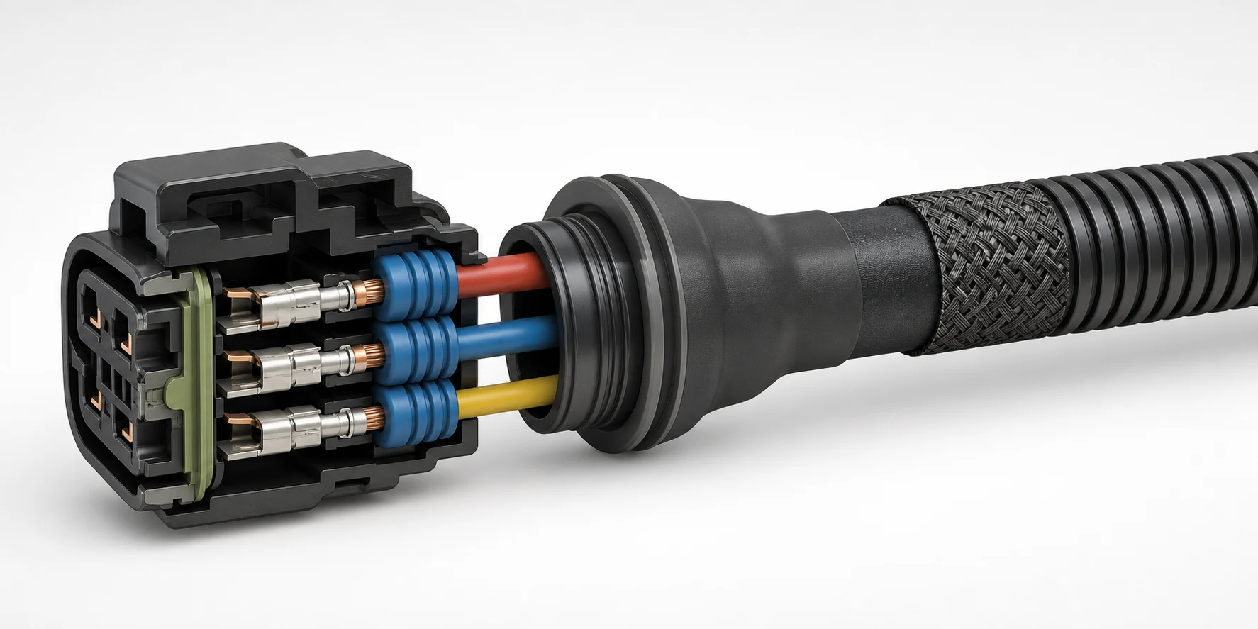
The housing, contact, wedge lock, cavity plug, and seal must form a compatible system. Confirm the wire-size range, insulation diameter range, plating, mating-cycle expectation, polarization, terminal position assurance, and service method. For sealed connectors, an apparently small mismatch between wire insulation diameter and seal range can defeat ingress performance.
Use the contact manufacturer’s application specification to define strip length, crimp tooling, conductor crimp height or width, insulation support, pull-test method, and visual acceptance. Those values are terminal- and wire-specific. A generic “automotive crimp” number is not technically defensible.
Routing, protection, and branch geometry
Control the harness on the drawing in the same state in which it will be measured. Identify datum points, tolerances, breakout directions, clip orientation, label zones, tape overlap, sleeve termination, and permitted float. Protect edges and high-motion zones with the appropriate loom, braid, conduit, tape, grommet, or overmolded strain relief.
Branch length is not merely cosmetic. A short branch can preload a connector or prevent service access. Excess length can rub, snag, or enter a hot zone. The supplier’s assembly board should control geometry without forcing the harness into a shape that hides accumulated tolerance.
What Manufacturing Controls Matter Most?
The most important controls connect each process parameter to a drawing requirement or component specification. Effective production covers incoming material identity, controlled cutting and stripping, validated terminal tooling, documented crimp setup, connector loading, splice and solder controls where applicable, branch-board assembly, protection, labeling, electrical testing, and final inspection.
Incoming material and lot identity
Verify wire, terminal, connector, seal, sleeve, tape, and label materials against the released BOM. Record manufacturer part number, supplier lot, date code where relevant, and the work order that consumed the material. Counterfeit or mixed terminals can create intermittent failures even when housings look identical.
Material substitutions require a defined approval path. A replacement wire or connector may change crimp settings, seal compatibility, temperature capability, chemical resistance, color, mating behavior, or regulatory status. Commercial availability alone is not evidence of equivalence.
Cutting, stripping, and wire preparation
Control cut length, strip length, nicked strands, insulation damage, and conductor deformation. Small conductors deserve particular attention because minor tool wear or feed variation consumes a larger share of the available process window. TE Connectivity’s small-wire crimping guidance highlights the quality challenges created by smaller termination geometry and the need for appropriate application tooling.
Crimping and setup verification
Use the correct terminal, applicator, anvil, crimper, wire, and setup. Verify the crimp at startup, after tooling adjustment, after material change, and at the frequency defined by the control plan. Relevant checks may include crimp height, crimp width, conductor brush, bellmouth, cutoff tab, insulation position, terminal deformation, pull force, and cross-section analysis.
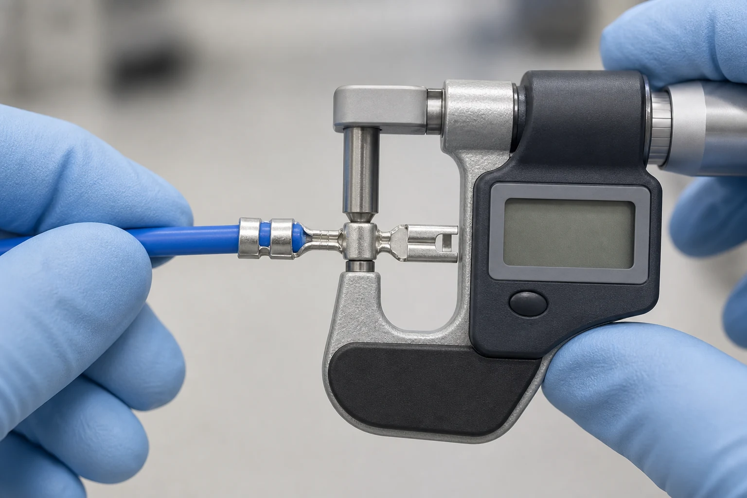
Crimp height is a process indicator, not a universal performance guarantee. Pull force provides different evidence, and neither test alone proves sealing, retention, electrical stability, or vibration durability. The control plan should combine setup verification, periodic measurement, visual inspection, and product testing appropriate to the risk.
| Defect | Likely cause | Detection method | Prevention or control |
|---|---|---|---|
| Crimp height outside specification | Tool setting, wear, wrong wire, wrong terminal, or feed variation | Crimp-height measurement and trend review | Locked setup, verified materials, preventive maintenance, startup and periodic checks |
| Low pull-out force | Missing strands, under-crimp, wrong contact, short strip, or poor conductor placement | Defined pull-force test with correct preparation | Strip-length control, conductor-position check, matched tooling, setup approval |
| Wrong pin or crossed circuit | Loading error, ambiguous pinout, or uncontrolled rework | Automated continuity and point-to-point test | Clear cavity map, keyed fixtures, independent verification, controlled rework |
| Open or intermittent circuit | Incomplete insertion, damaged conductor, poor splice, or terminal back-out | Continuity test, retention check, and application-specific stress test | Secondary-lock verification, splice control, routing protection, terminal seating check |
| Short circuit | Stray strands, insulation damage, incorrect splice, or pinout error | Short-circuit test and visual inspection | Strip control, protected routing, clean work area, test fixture coverage |
| Seal or insulation damage | Wrong seal range, terminal flash, sharp edge, or insertion damage | Magnified visual inspection and applicable sealing validation | Compatible component system, tooling maintenance, insertion aids, handling standard |
| Branch dimension out of tolerance | Incorrect board, datum, tape buildup, or operator routing | Fixture and final dimensional inspection | Revision-controlled board, clear datums, first-piece approval, change control |
What Testing Strategy Should the Buyer Require?
Testing should separate design validation from routine production inspection. Design validation demonstrates that the selected construction can survive defined electrical, mechanical, environmental, and sealing stresses. Production testing screens each unit for manufacturing errors. Sampling, frequency, limits, fixtures, and retained records must come from the customer specification and risk analysis.
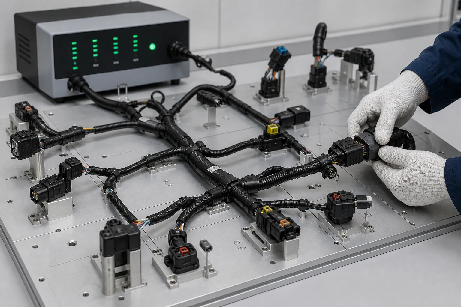
A basic end-of-line test commonly checks continuity and unintended shorts across the complete pin map. Depending on circuit voltage, insulation system, connector design, and customer requirements, the plan may also include insulation resistance, dielectric withstand, contact resistance, functional loads, shield checks, or component presence. Test voltage and limits must be approved for the circuit; applying a generic hi-pot routine can damage sensitive electronics.
| Test or evidence | Primary purpose | Typical stage | Important boundary |
|---|---|---|---|
| Point-to-point continuity and shorts | Detect wrong pins, opens, shorts, and some splice errors | Every production unit when specified | Does not prove environmental durability or crimp geometry |
| Crimp-height and visual checks | Confirm termination process setup and workmanship | Startup and control-plan frequency | Limits must come from the terminal and wire combination |
| Pull-force test | Evaluate mechanical retention of the termination | Setup validation and defined sampling | Sample preparation and test method affect results |
| Insulation resistance or dielectric withstand | Check isolation and insulation integrity | Qualification or production when specified | Test level must suit the product and connected devices |
| Connector retention and seal validation | Confirm locking, sealing, and mechanical interfaces | Design or process validation | Requires the correct mating parts and customer method |
| Vibration, thermal, fluid, or ingress testing | Demonstrate performance in the intended environment | Design validation or qualification | Conditions must reflect mounting location and customer standard |
| Functional test | Confirm behavior with loads, modules, sensors, or simulated interfaces | Validation or production when risk justifies it | Fixture design and software revision require control |
Require a test fixture map and a method for verifying that the fixture itself has not failed. Challenge fixtures with known open, short, and miswire conditions before release and at controlled intervals. Store test results by work order, date, fixture revision, and product serial or lot when traceability is required.
How Should Procurement Evaluate a Potential Supplier?
Procurement should evaluate evidence rather than capability slogans. Ask the manufacturer to demonstrate drawing control, component verification, tooling ownership, process setup, operator training, measurement-system control, test-fixture validation, nonconformance handling, traceability, change notification, and production capacity for the quoted volume. Match the audit depth to product risk and customer requirements.
Start with a document review, then verify the process on a representative assembly. A generic certificate cannot prove that the specific terminal applicator is maintained, the pinout test covers every circuit, or an approved alternate is controlled. Conversely, a capable low-volume supplier may be suitable without owning every environmental laboratory if qualified third-party testing is planned and documented.
| Supplier question | Evidence to request | Why it matters |
|---|---|---|
| How do you review drawings and BOMs before quoting? | DFM checklist, assumption log, controlled quote review | Exposes ambiguity before tooling and material commitments |
| How are terminal and applicator combinations released? | Setup sheet, application specification, sample measurements, maintenance record | Connects tooling settings to component requirements |
| How do you prevent pinning errors? | Work instruction, cavity map, fixture coverage, challenge-part record | Reduces wrong-circuit escapes |
| What does “100% electrical test” include? | Test specification, pin map, limits, fixture revision, result format | Separates a real test plan from a marketing claim |
| How are changes approved? | Engineering change process and customer-notification rules | Prevents silent component or process substitutions |
| What is traceable? | Example traveler, material lot record, inspection report, product label | Supports containment and root-cause analysis |
| Can prototypes transfer to production? | Process flow, control plan, capacity and tooling plan | Avoids an uncontrolled hand-built prototype becoming the production baseline |
| Which automotive submissions are supported? | Customer-specific PPAP responsibility matrix and sample package | Aligns expectations before launch |
If the program requires Production Part Approval Process (PPAP), define the submission level and customer-specific requirements in the purchase documents. AIAG describes PPAP as the industry standard for demonstrating that engineering design records and specification requirements can be met consistently during an actual production run at production rates. Do not assume that “PPAP available” means every required record is included.
For IATF 16949, verify the certificate number, legal entity, manufacturing address, scope, issue and expiry dates, and accredited certification body. The IATF customer-specific requirements portal also shows why an automotive quality system does not eliminate OEM-specific obligations.
How Do Prototypes Move Into Controlled Production?
A reliable transfer freezes the approved design, materials, tooling, process settings, inspection plan, test program, labeling, and packaging before recurring production. The manufacturer should identify which prototype steps were manual, which will be automated, and whether that change affects geometry, termination, sealing, appearance, or validation evidence.
Use prototypes to verify fit, form, function, assembly access, routing, mating, serviceability, and test strategy. Record every deviation from the intended production process. After approval, release a controlled drawing package and golden sample only when the sample’s role is clear. A golden sample should illustrate agreed workmanship or appearance; it must not override dimensional or material requirements unless the drawing says so.
Before scale-up, review capacity for wire processing, crimping, connector loading, assembly boards, test fixtures, inspection, and packaging. Confirm backup tooling and maintenance for constrained operations. Revalidate when a material, tool, process, fixture, site, or specification change can affect product performance.
What Drives Cost and Lead Time?
Material availability, connector allocation, terminal reels, wire minimums, custom tooling, assembly labor, test complexity, documentation, and order profile usually drive cost more than total cable length alone. The fastest quotation is not always the fastest launch; an assumption-free quote can become expensive after engineering questions appear.
Cost improves when the design uses compatible, available components; dimensions have functional tolerances; branches are easy to fixture; labels and coverings are standardized; and the test plan targets real risks. Cost rises with sole-source components, frequent changeovers, complex shield terminations, tight cosmetic rules, extensive overmolding, unusual packaging, and customer-specific reporting.
Ask for separate pricing for recurring parts, tooling, fixtures, first articles, validation, PPAP, and expedited material. Also request the material lead-time assumptions and quote validity. This makes alternative proposals comparable and prevents a low unit price from hiding nonrecurring charges.
How OUKETECH Can Support an Automotive Cable Assembly Project
OUKETECH provides comprehensive, end-to-end solutions for custom automotive wiring harnesses and cable assemblies—developed entirely in-house—covering the full project lifecycle. We independently handle every stage: drawing analysis, precise BOM verification, standardized pin-out design, custom sample fabrication, prototype vehicle integration and testing, and standardized mass production and delivery. We fully execute custom projects to meet the specific wiring harness and cable assembly needs of diverse clients.
In production and quality control, we employ a mature, standardized process system. We offer one-stop services including precision wire cutting, accurate stripping, high-precision terminal crimping, professional overmolding, comprehensive electrical performance testing, and complete technical documentation archiving. We feature standardized collaboration workflows, robust testing protocols, comprehensive industry certifications, stable mass-production capacity, and a proven track record of successful projects. All service standards are confirmed and formalized during the RFQ review stage, ensuring full compliance with project specifications and regulatory requirements.
Our core service portfolio encompasses the full spectrum of automotive wiring harness customization, custom cable assemblies, non-standard harness manufacturing, OEM-compatible cable production, and molded cable assembly customization. We provide mature, actionable technical support and production capabilities for a wide range of automotive wiring projects. All services showcased on our website are part of a standardized system; project execution, technical specifications, delivery standards, and service commitments are governed strictly by the formal quotation and technical proposal confirmed by both parties, ensuring standardized processes, clear criteria, and well-defined roles and responsibilities.
To efficiently complete the Design for Manufacturability (DFM) review and provide an accurate, formal quotation, clients simply need to submit a complete project data package. Essential information includes: wiring harness drawings, BOMs, precise part numbers for connectors and terminals, complete circuit specifications, standardized pin-out charts, specific requirements for sample fabrication, annual procurement volumes, and acceptance criteria for specialized testing. At the same time, clients can provide customized requirements—such as vehicle installation parameters, proprietary technical standards, PPAP (Production Part Approval Process) requirements, established project delivery schedules, and alternative approval protocols. We will strictly adhere to all project details to tailor a dedicated, feasible, and mass-production-ready manufacturing and delivery plan, ensuring standardized execution throughout the entire process.
Engineer and Buyer Checklist
Use this checklist before releasing a custom automotive cable assembly RFQ:
- Define the circuit function and vehicle mounting location.
- Release a revision-controlled drawing, BOM, and pinout.
- Specify approved connector, terminal, seal, wire, and covering systems.
- Identify electrical loads, shielding, grounding, and isolation requirements.
- Define temperature, vibration, fluids, abrasion, ingress, flex, and service conditions.
- State dimensional datums, tolerances, branch directions, clips, labels, and packaging.
- Require terminal-specific crimp settings and inspection evidence.
- Separate design validation from routine production testing.
- Define continuity, shorts, insulation, functional, and fixture-validation requirements.
- Agree on first article, PPAP, traceability, retention, and change notification.
- Review prototype-to-production differences before approval.
- Confirm capacity, tooling ownership, material lead time, and approved alternates.
FAQ
Is an automotive cable assembly the same as a wire harness?
The terms overlap, and IPC notes that cable and wire harness may be used interchangeably within its standard. In procurement, “cable assembly” often describes a connectorized cable with added protection or defined signal characteristics, while “wire harness” often emphasizes routed branches and bundled discrete wires. The drawing and BOM should remove ambiguity.
What files are needed to quote a custom automotive cable assembly?
Send a controlled drawing, BOM, pinout, connector and terminal part numbers, wire specifications, annual volume, environmental conditions, testing requirements, packaging rules, and launch schedule. Add mating information and a physical sample when available. Ask the manufacturer to return assumptions and unresolved technical questions with the quote.
Should every automotive cable assembly receive a hi-pot test?
No. The test method and voltage must match the circuit, insulation system, connected devices, customer specification, and product risk. Continuity and short-circuit checks are common production screens, but dielectric withstand or insulation-resistance testing should be applied only under an approved technical requirement.
How is crimp quality verified?
Use the terminal manufacturer’s application specification and an approved control plan. Evidence may include crimp height, width, conductor brush, bellmouth, cutoff tab, insulation support, visual criteria, pull force, and cross-section analysis. No single generic value applies to every terminal and wire combination.
What is the difference between first-article approval and PPAP?
First-article inspection normally verifies selected characteristics on initial parts. PPAP is a broader automotive production-approval process that can include design records, process flow, FMEA, control plan, measurement evidence, capability results, material and performance records, samples, and customer-specific submissions. Scope must be agreed with the customer.
How can a buyer verify an IATF 16949 claim?
Request the current certificate and check the legal entity, site address, manufacturing scope, issue and expiry dates, and certification body. Confirm that the quoted product is manufactured within that scope. Also review the end customer’s specific requirements because a quality-system certificate does not replace them.