

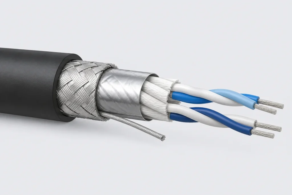
During the mass production and commissioning of automated equipment, inspection instruments, vision systems, and RF industrial control devices, the most common yet difficult-to-troubleshoot hidden faults are not hardware failures, but signal anomalies caused by electromagnetic interference (EMI). Specific symptoms include fluctuating sensor data, analog signal drift, intermittent communication, servo motor jitter, false equipment alarms, unstable high-frequency testing, and PLC signal loss.
Many enterprises repeatedly replace controllers, install filters, or add ferrite beads, yet fail to permanently resolve the issue. The root causes lie in incomplete cable harness shielding, incorrect grounding methods, and disorganized cable routing. Issues such as the use of standard unshielded harnesses, floating shields (unconnected at one end), chaotic multi-point grounding, and the mixing of high-voltage and low-voltage lines turn cables into “receiving” and “radiating” antennas. This continuously amplifies electromagnetic noise, resulting in failure to meet EMC standards and poor equipment stability.
OUKETECH specializes in the customization of non-standard industrial shielded harnesses and EMC-focused harness remediation. Addressing on-site issues—such as severe interference, signal instability, test data drift, and excessive EMC radiation—we provide a comprehensive, one-stop solution that combines custom shielded harnesses, standardized grounding schemes, and system-wide cable routing optimization, effectively eliminating electromagnetic interference at the source.
一、Three Root Causes Related to Wiring Harnesses Behind Frequent Electromagnetic Interference in Equipment (90% of Equipment Falls into These Pitfalls)
Interference in industrial settings is not merely an environmental issue; the vast majority of cases stem from systemic defects caused by improper wiring harness design and installation:
- Ineffective or incorrect grounding of the shielding layer
Common issues include grounding the shield haphazardly at both ends, leaving it completely floating, grounding it via a break in the insulation mid-run, or having a loose/poor connection at one end. Grounding low-frequency signal shields at both ends creates ground loop interference, generating induced currents that cause signal drift; conversely, grounding high-frequency signal shields at only one end leaves the shield floating, preventing the dissipation of high-frequency noise and resulting in severe radiated interference. - Incomplete shield termination and breaks in 360° shielding
Standard processing methods—such as excessive stripping, improper folding back of the shield, exposed conductors, or loose crimping—can create “gaps” in the shielding layer. High-frequency electromagnetic signals leak out or couple in through these gaps, rendering the entire shielded harness ineffective; this is also a primary cause of radiated emission failures in EMC testing. - Lack of isolation between high-voltage/high-power lines and low-voltage signal lines
Running power lines, servo power cables, or high-current solenoid valve cables in parallel over long distances—or within the same conduit—alongside RS-485, CAN, analog, or sensor signal lines allows high-power interference to couple directly into low-voltage signal circuits. This results in unstable communication, fluctuating data readings, and intermittent equipment errors.
二、OUKETECH Custom Shielded Wire Harnesses: Layered shielding structure for noise reduction at the source.
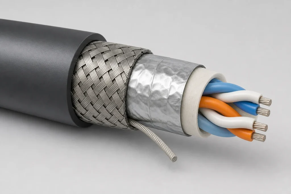
To address the complex electromagnetic environments encountered by industrial equipment, OUKETECH avoids the indiscriminate use of standard single-layer shielded cables. Instead, we select specific shielding solutions—ranging from single-layer aluminum foil and copper braid to dual-layer composite shielding—tailored to the equipment’s interference levels, signal types, and frequency ranges, thereby ensuring high-interference-rejection signal transmission.
- Precision Equipment Handling Low-Level Signals | Dual-Layer Composite Shielding
Designed for applications involving low-level signals, such as sensors, analog data acquisition, visual inspection systems, and precision instruments. Features a dual-layer shielding structure combining full-coverage aluminum foil with high-density copper braiding (shielding coverage ≥98%) to block external electric fields, magnetic fields, and RF interference, effectively eliminating signal drift and elevated noise floors. - High-Frequency Communication & Motion Control | High-Density Braided Shielding
Suitable for CAN, RS-485, EtherCAT, pulse signal, and servo feedback harnesses. The high-density braided structure offers superior resistance to high-frequency radiation, effectively suppressing crosstalk and resonance interference during high-speed signal transmission to ensure stable, continuous communication. - Dynamic Motion Equipment | Integrated Shielding for Flexing Applications
Engineered for robotic arms, cable carriers, and reciprocating machinery, this solution utilizes a flexible shielding structure. It prevents the breakage or shield delamination often seen in standard shielded harnesses during bending, maintaining consistent shielding effectiveness even under dynamic operating conditions.
三、OUKETECH Standardized Grounding Remediation Plan (Precisely Matched to Operating Conditions)
For shielded wire harnesses to effectively resist interference, the choice of shielding material is fundamental, while the grounding termination process is critical. Adhering to industry-standard EMC protocols such as IEC 61000, OUKETECH implements tailored grounding strategies for specific signal scenarios, completely eliminating ground loops and interference caused by floating grounds.
- Low-frequency analog signals | Single-ended grounding near the source (eliminates ground loops)
For low-frequency, low-level signals—such as 4–20mA or 0–10V analog signals, as well as temperature and pressure sensor inputs—a unified approach is used: grounding at the signal source end while leaving the shield floating at the load end. This prevents potential differences between the two points from creating loop currents, thereby completely resolving issues with data drift and fluctuation. - High-frequency digital/communication signals | Dual-ended 360° grounding (dissipates high-frequency noise)
For high-speed pulses, bus communications, and high-frequency detection signals, the shield is fully grounded at both ends. This creates a low-impedance path to dissipate high-frequency noise, suppresses radiated emissions and signal resonance interference, and ensures suitability for high-frequency, high-speed transmission environments. - Long-distance routing across cabinets | Capacitive isolation grounding
For cable runs exceeding 10 meters or those spanning multiple cabinets or zones, a hybrid grounding method is employed: direct grounding at one end and capacitive isolation grounding (using a 100nF high-frequency capacitor) at the other. This configuration dissipates high-frequency noise while blocking DC ground loops, effectively solving interference challenges associated with long-distance transmission. - Critical process: 360° continuous termination
All OUKETECH shielded wire harness terminations undergo a strict 360° circumferential crimping process. The shield remains continuous with no exposed copper or loose strands, preventing interference leakage caused by gaps in the shielding and ensuring superior, stable EMC performance for the entire system.
Guidelines for Rectifying System-Level Cable Routing and Layout (for Rapid Interference Reduction)
Once grounding and shielding are properly implemented, cable routing and layout serve as the final critical line of defense. OUKETECH’s on-site rectification follows three key principles:
- Complete separation and isolation of high-voltage and low-voltage circuits
Power cables, servo power lines, and solenoid valve cables must be routed in separate conduits or cable trays from signal and communication cables. Bundling them together in parallel over long distances is prohibited; a minimum parallel separation of 200mm (or 10 times the cable’s outer diameter) is recommended. Where paths must cross, they should do so at a 90-degree angle to prevent coupling interference. - Elimination of coiled excess cabling
Excess cables must not be coiled or stacked; coiling creates an inductive loop that amplifies electromagnetic noise, turning minor interference into severe disruption. During rectification, all cables must be straightened and routed neatly. - Comprehensive grounding of connector shielding
All metal connector housings, shielding shells, and terminal bases must be reliably connected to protective earth (PE). This ensures the integrity of the system’s shielding enclosure, eliminating gaps or floating potentials.
五、 Advantages of OUKETECH’s Wire Harness Rectification & Customization Services
Typical applications include equipment requiring high signal stability, such as semiconductor inspection systems, medical devices and laboratory analytical instruments, visual inspection and AOI systems, BMS testing equipment for new energy, industrial robots and CNC systems, automated production lines for photovoltaics and lithium batteries, and RF/microwave testing instruments.
While most wire harness manufacturers focus solely on production without expertise in EMC remediation, OUKETECH prioritizes equipment stability and interference immunity, offering technical, customized services:
- Customized shielding levels based on operating conditions: We avoid “one-size-fits-all” solutions, instead matching shielding structures and grounding schemes to the specific interference environment, signal types, and motion dynamics of the equipment.
- Solutions for EMC compliance issues: We address non-compliance in EMC testing—supporting product shipment, certification, and system-level remediation—to effectively mitigate radiated and conducted interference.
- Support for small-batch prototyping and rapid remediation: We provide quick-turnaround support for new product development, prototype debugging, and the retrofitting of existing equipment.
- Technical implementation and delivery: We provide recommendations on cable routing, grounding specifications, and installation guidance; our products are ready for immediate installation, effectively resolving persistent interference issues.
六、Conclusion
Repeated attempts to rectify electromagnetic interference (EMI) often fail because the root cause lies not in the equipment itself, but in systemic issues such as ineffective cable harness shielding, improper grounding, and non-standardized cable routing. Replacing existing cabling with OUKETECH’s custom shielded harnesses—combined with standardized grounding and routing corrections—can fundamentally resolve interference-related faults, including signal drift, intermittent communication, false equipment alarms, and EMC non-compliance.
If your automation equipment, testing instruments, or industrial control systems are experiencing issues like severe EMI, signal instability, or anomalous test data, and you require a tailored shielded harness solution and EMC-compliant routing plan, please contact the OUKETECH technical team. We offer complimentary services including: ① operational environment assessment and preliminary identification of interference sources; ② recommendations for shielded harness selection; ③ grounding and routing rectification plans; and ④ prototyping timelines and precise quotations. We can quickly initiate the process based on your drawings, photos, or on-site videos.