OUKETECH supplies custom fiber optic cable assemblies for OEM equipment and network integration. Share the mating ports, cable route and optical requirements so we can review a pre-terminated assembly against your drawing, BOM or sample.
We confirm the connector and fiber combination, finished length, sample plan and inspection scope during quotation.
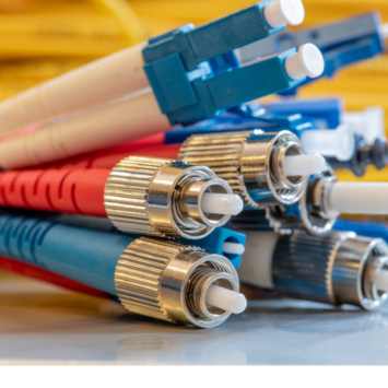
Bring the equipment interfaces and the installation route to the review. Each connector and cable construction is confirmed for the project.
For equipment bays and patch panels, call out connector and polish at both ends, simplex or duplex construction, and the finished length. For shallow enclosures, check the boot and bend clearance behind the port.
For parallel optics and dense panels, specify the fiber count, pinning and key orientation at each end, and the position-to-position fiber map. Check the route and connector clearance before locking the trunk length.
For a trunk-to-duplex or multi-port fanout, identify the port at the end of each leg. Specify staggered leg lengths where ports sit at different distances, and show where the breakout body can be secured.
Identify the transceivers or optical interface and specify the required fiber, such as OS2 single-mode or OM3/OM4 multimode. List the wavelengths at which the assembly must be tested.
Call out the manufacturer and part number where known. For LC or SC, specify UPC or APC separately at each end and match each end to its intended mating port.
Show the transmit and receive paths on a duplex assembly. For MPO or fanout, provide an end-to-end fiber map and identify the connector orientation used to number positions.
A custom length fiber optic cable drawing should identify the two measurement points. Add the tolerance, breakout position and individual leg lengths where applicable.
State the jacket requirements and installation conditions. Show the tightest bend, cable entry, boot clearance and any pulling constraint. Check bend limits for both installation and service against the selected cable construction.
Define end labels, leg IDs and any serial or lot marking. Specify dust caps and how assemblies should be coiled and packed if the installation team needs to pull or stage them in a particular order.
Specify the insertion-loss limit per path in dB and the test wavelengths. Where reflections matter to the equipment, give the return-loss requirement and the measurement method. Identify the reference setup, test direction and whether the report must show results for each fiber.
Check end-face condition, optical loss and fiber mapping as separate acceptance items. An assembly may pass a loss check and still route transmit to the wrong port. For multifiber assemblies, confirm the reference cords and mating setup for the specified connector pinning and polish.
Evaluate the first sample in the actual routing path or a representative fixture. Verify the connectors can be inserted and removed with neighboring ports populated, and that the bend and breakout fit once the cover is closed.
For broader sourcing, see custom cable assembly manufacturing and telecom cable assemblies. Use the cable assembly drawing checklist to organize part numbers, revisions and approvals.
OUKETECH reviews the endpoints, fiber type, cable path and component availability. If an alternate part is proposed, confirm fit and optical requirements before approval.
Agree on sample quantity, drawing revision and acceptance checks. Confirm any per-fiber report, end-face images or traceability requirements as part of the quote.
After sample approval, tie the order to the approved parts, fiber map, dimensional tolerances and inspection plan. Review material availability and lead time for the requested volume.
Yes, as a drawing requirement when the two ports call for different polishes. Each connector must mate with the correct polish at its own port. Confirm the exact connectors and availability during review.
It is enough to start a review. Include the port or transceiver part numbers, a route sketch and your sample quantity. The connector, fiber type and test limits need to be agreed before a build can be quoted against a released specification.
Ask for the assembly price by quantity, any one-time setup or sample cost, and the scope of optical testing and documentation. Clarify whether a report is required for each assembly or lot. Connector availability and the reporting scope can affect both price and lead time.
Attach the drawing, BOM or fiber map if available. Include the connector and polish at both ends, fiber type and count, finished length, polarity, test limits, sample and production quantities, and delivery destination.
If you are still defining the assembly, send the mating port part numbers and the route or enclosure dimensions. We can use those details to identify what needs to be confirmed for a quote.