

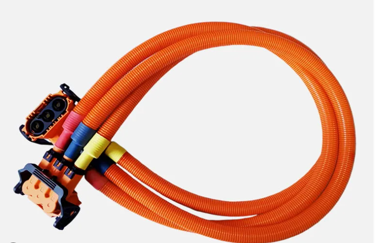
Component failure in custom wire harnesses rarely stems from a single catastrophic flaw. More often, it is the cumulative result of small oversights during early design and material selection: an under-rated terminal plating here, an improper strain relief boot there, or insulation that hardens and cracks under localized heat exposure.
For sourcing teams and hardware development engineers, specifying components is a delicate balancing act between electrical performance, harsh-environment survivability, and manufacturing scalability. Selecting off-the-shelf parts without considering mating cycles or crimp integrity frequently leads to production delays, premature field failures, and unexpected cost overruns.
Building a dependable interconnect assembly requires treating every sub-component as part of a single, integrated electrical system. This guide breaks down the critical selection criteria for each layer of a modern harness—from raw conductor sizing to mechanical strain relief—to streamline your procurement process and protect your equipment’s field performance.
2. Core Anatomy of an Industrial Wire Harness
Related OUKETECH resources: custom wire harness manufacturing.
+-------------------------------------------------------------------------+
|                       CORE WIRE HARNESS ANATOMY                         |
+-------------------------------------------------------------------------+
|                                                                         |
|  [ Conductor ] ---> [ Terminal / Pin ] ---> [ Connector Housing ]       |
|        |                                           |                    |
|        v                                           v                    |
|  [ Insulation & Sleeving ] -----------> [ Strain Relief & Grommets ]    |
|                                                                         |
+-------------------------------------------------------------------------+
Conductors and Primary Wiring
The foundation of any wire assembly begins with the conductor core. Material selection directly governs current capacity, signal integrity, and mechanical flexibility:
- Bare Copper: High conductivity, cost-effective, but vulnerable to oxidation at elevated temperatures.
- Tinned Copper: Offers superior corrosion resistance and ease of soldering; highly recommended for industrial and marine applications.
- Strand Configuration: Coarse stranding (e.g., 7 or 19 strands) works well for static runs. Fine or extra-fine stranding (e.g., Type K or continuous-flex copper) is necessary for high-flex robotics or dynamic machinery to prevent metal fatigue.
When high-power distribution is required, integrating pre-engineered Battery Cable Assemblies ensures low voltage drop and proper gauge sizing (AWG 4/0 down to 8 AWG) for heavy-duty power lines.
Connectors, Housings, and Pin Terminals
Connectors define how easily a harness integrates into your final product during assembly:
- Contact Plating: Gold-plated pins excel in low-voltage, low-current signal lines where fretting corrosion must be avoided. Tin or nickel platings suit high-power or general industrial interfaces.
- Retention Mechanisms: Positive-locking latch housings prevent accidental disconnects caused by continuous vibration.
- Terminal Crimp Profile: Crimp height and width must align strictly with terminal manufacturer specifications to achieve a gas-tight mechanical bond.
Insulation, Sleeving, and Protective Conduit
Outer protection shields vulnerable conductors from chemical exposure, abrasion, and thermal degradation:
| Protection Type | Material Options | Primary Benefit | Best Used For |
|---|---|---|---|
| Primary Insulation | PVC, XLPE, Teflon (PTFE) | Electrical isolation, temperature rating | Internal hook-up wiring |
| Braided Sleeving | PET Monofilament, Fiberglass | Abrasion resistance, flexible bundling | High-flex wire routing |
| Corrugated Conduit | Polyamide (PA6/PA12), Polypropylene | Crush resistance, fluid protection | Exposed machinery, engine bays |
| Heat Shrink Tubing | Dual-wall Polyolefin (Adhesive-lined) | Moisture sealing, strain relief | Terminal transitions, splices |
Strain Relief, Grommets, and Mounting Hardware
Mechanical stress at termination points accounts for a high percentage of field failures. Utilizing overmolded boots, strain relief backshells, or rubber grommets prevents tight bend radii right at the connector base. For complex, multi-branch enclosures, custom-built Custom Wire Harness Assemblies utilize strategically placed edge clips, cable ties, and mounting pucks to ensure simple, drop-in installation on the OEM assembly line.
3. Critical Environmental & Electrical Evaluation Factors
Selecting harness components based solely on room-temperature bench tests is a recipe for field failure. System designers must evaluate real-world operating conditions:
                  ┌───────────────────────────────┐
                  │ Environmental & Electrical    │
                  │ Selection Criteria            │
                  └───────────────┬───────────────┘
                                  │
    ┌────────────────┬────────────┼────────────┬────────────────┐
    │                │            │            │                │
    ▼                ▼            ▼            ▼                ▼
┌───────┐      ┌──────────┐  ┌──────────┐  ┌───────┐      ┌──────────┐
│Thermal│      │ Electrical│  │ Mechanical│  │Ingress│      │ Chemical │
│Limits │      │  Loads   │  │   Flex   │  │ (IP)  │      │ Exposure │
└───────┘      └──────────┘  └──────────┘  └───────┘      └──────────┘
- Thermal Operating Limits: Verify both continuous operating temperature and peak exposure limits. Standard XLPE wire handles up to 125°C, whereas Teflon (PTFE/PFA) insulation is required for environments exceeding 200°C.
- Electrical Load & Voltage Drop: High-power circuits need careful derating based on bundle density. Running multiple high-current conductors within a tight protective sheath traps heat, lowering overall current-carrying capacity.
- Mechanical Stress & Motion: Identify whether the application involves static routing, occasional maintenance flexing, or continuous multi-axis motion. Dynamic applications require flex-rated jacket materials (PUR/TPE) and specialized strain relief.
- Ingress Protection (IP Ratings): Sealed connectors rated IP67 or IP68 utilize silicone wire seals and perimeter gaskets to keep out water, dust, and cleaning solvents in washdown environments.
- Chemical & UV Exposure: Solar installations and outdoor equipment demand UV-stabilized jacketing. Industrial automation setups require resistance to hydraulic fluids, cutting oils, and fuels.
4. Manufacturing Quality Standards & IPC Compliance
An optimized bill of materials (BOM) is only as good as the quality standards governing its assembly. To guarantee consistency across high-volume production runs, insist on the following industry benchmarks:
- IPC/WHMA-A-620 (Class 2 & Class 3): The global standard for cable and wire harness acceptability. Class 2 covers standard commercial/industrial electronics, while Class 3 applies to high-reliability systems where continuous performance or harsh environments are mission-critical.
- UL Wiring Harness Traceability (ZPFW2/ZPFW8): Ensures all raw materials—wires, connectors, sleeving—are UL-certified and traceable through every step of production.
- RoHS & REACH Compliance: Mandatory for products destined for European or international markets, restricting hazardous substances like lead, cadmium, and specific phthalates.
- Automotive & Industrial Quality Systems: Manufacturing facilities holding IATF 16949 or ISO 9001 certifications demonstrate strict process controls, automated crimp-force monitoring (CFM), and 100% electrical continuity testing.
5. B2B Procurement & Cost-Optimization Checklist
Procurement managers often face trade-offs between component cost, lead times, and assembly labor. Use this practical evaluation checklist during component selection to keep costs under control without sacrificing quality:
[ ] Standardize Component Selection
Opt for off-the-shelf, widely stocked connector series (e.g., TE Deutsch, Molex, Amphenol) to minimize component lead times and avoid high MOQs.
[ ] Evaluate Terminal Tooling Availability
Confirm your contract manufacturer holds existing applicator tooling for selected terminals to eliminate non-recurring engineering (NRE) tooling fees.
[ ] Optimize Wire Gauge and Insulation Types
Consolidate wire types across harness designs to maximize raw material purchasing leverage.
[ ] Plan for Ingress Sealing Only Where Required
Apply costly IP68 or overmolded connectors exclusively to exposed areas; use standard unsealed housings for protected internal electronics.
[ ] Conduct Design for Manufacturability (DFM) Reviews
Engage your wire harness assembly partner early in the design phase to spot tight bends, overly complex breakouts, or obsolete components before sign-off.
6. Partnering with the Right Cable Assembly Manufacturer
A robust component strategy requires an experienced manufacturing partner capable of turning complex schematics into reliable physical products. From rapid prototyping and DFM feedback to automated testing and scalable production, working with an established custom wire harness specialist protects your supply chain from unexpected disruptions.
Whether you need specialized power distribution configurations, high-flex signal runs, or fully ruggedized industrial assemblies, selecting certified components aligned with IPC-A-620 standards ensures long-term operational success for your product line.