

How to Select a Coaxial Terminator: An Engineer’s Guide for B2B Buyers
A coaxial terminator closes an unused RF port with a load matched to the system impedance. That small component can prevent reflections, reduce an open port’s exposure to unwanted RF energy, and give test equipment a defined load. For a procurement team, however, “50 ohm SMA terminator” is not a complete specification. Connector gender, frequency, power, VSWR, environment and test evidence all affect whether the part will work in production.
This guide explains the engineering basics and turns them into a practical sourcing process—from preparing a coaxial terminator RFQ to sample approval and incoming inspection.
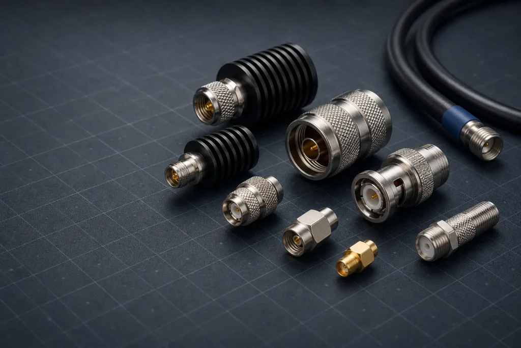
Coaxial terminators may share a similar metal body, but connector interface, impedance, frequency and power ratings determine where each part can be used.
What Is a Coaxial Terminator?
A coaxial terminator—also called an RF terminator, termination load or matched load—is fitted to the end of a transmission line or directly onto an RF port. Inside is a resistive element designed to present the system’s nominal characteristic impedance, normally 50 Ω or 75 Ω.
When an RF signal reaches a load that matches the transmission line, most of the incident energy is absorbed by the load and converted to heat. When the load is open, shorted or mismatched, part of that energy travels back toward the source. This reflected energy can disturb measurements, create standing waves and reduce predictable signal transfer.
The word terminator does not describe one universal component. A low-power SMA male 50 ohm terminator used on a test fixture is a different product from a weather-sealed 75 ohm F-type terminator on a broadband port or a high-power RF termination load. The correct part is defined by the whole specification, not its appearance.
Why Open Coaxial Ports Matter
An unused port is an electrical discontinuity. On a splitter, coupler, amplifier, receiver or measurement fixture, leaving that port open may change the behavior expected by the network designer. The effect depends on topology, frequency, isolation between ports and the equipment design, so it should not be reduced to a universal claim that every open port causes the same amount of loss.
Open ports can also provide a path for ingress or egress. In broadband networks, unwanted RF energy entering through an unterminated connection may degrade the return path; energy leaking out can create a separate compliance or interference concern. Outdoors, an unprotected interface adds the mechanical risks of moisture, contamination and corrosion.
A matched coax terminator is therefore used when the equipment manual or RF design calls for a defined load. A terminator is not a repair for damaged cable, poor shielding or a defective connector. Those faults need to be found and corrected separately.
Coaxial Terminator vs Dust Cap, Shorting Cap and Dummy Load
These components may fit the same interface but do different jobs. Substituting one for another can invalidate a test or damage energized equipment.
| Component | Electrical condition | Primary purpose | Buyer warning |
|---|---|---|---|
| Matched coaxial terminator | Defined load, commonly 50 Ω or 75 Ω | Absorb RF energy and minimize reflections within its rated band | Verify impedance, frequency, power and connector interface |
| Dust or protective cap | Usually no defined RF load | Protect the mating interface from dust or handling damage | A metal cap is not automatically a terminator |
| Shorting cap | Intentional short circuit | Create a known short for a specific circuit or test method | Do not place on an active output unless the equipment permits it |
| RF dummy load | Matched load engineered to dissipate power | Test transmitters or absorb higher RF power | Confirm continuous power, peak power, cooling and duty cycle |
“Dummy load” and “terminator” sometimes overlap in supplier catalogs. Treat the datasheet as the authority: a miniature low-power terminator should never be assumed to handle transmitter output merely because its resistance is 50 Ω.
50 Ohm vs 75 Ohm Coaxial Terminators
The terminator must match the nominal impedance of the cable and equipment. A 50 Ω component is typical in radio, wireless infrastructure, antenna systems and RF test equipment. A 75 Ω component is typical in CATV, broadband, broadcast video and many CCTV installations. For more background on cable construction and impedance, see OUKETECH’s coaxial cable selection guide.
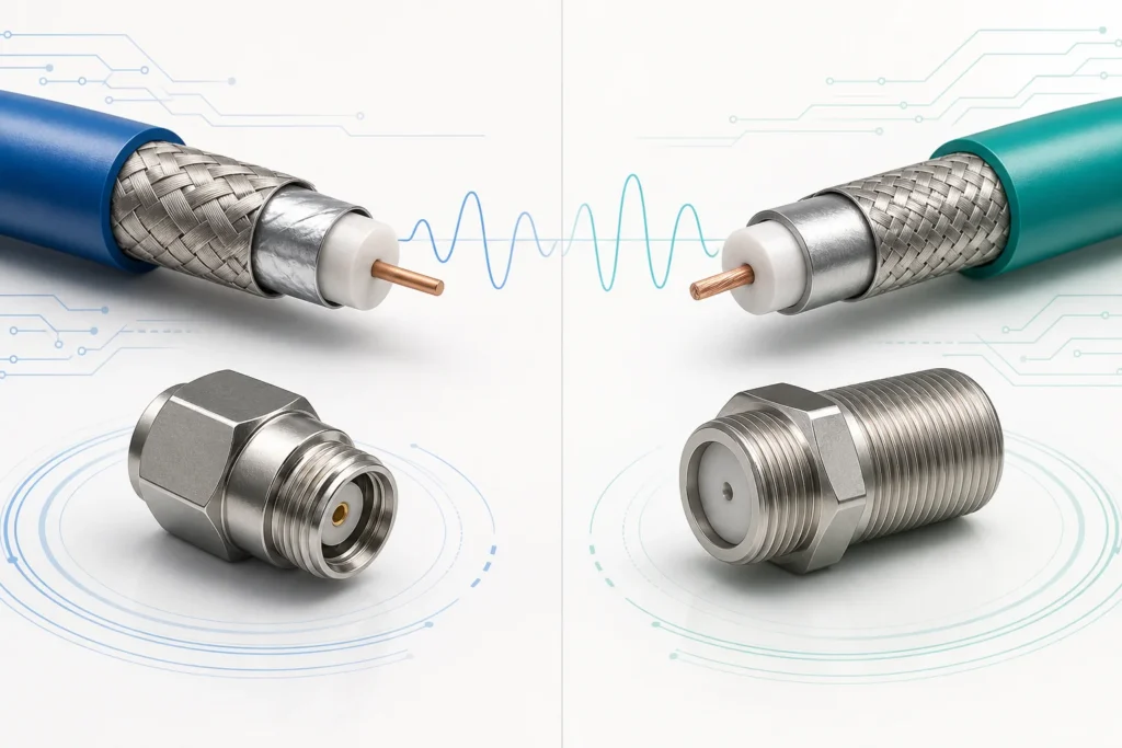
A 50 Ω and a 75 Ω transmission path require terminators matched to their respective system impedance; physical fit alone does not establish electrical compatibility.
| Selection point | 50 Ω terminator | 75 Ω terminator |
|---|---|---|
| Typical systems | RF communications, antennas, laboratory instruments, wireless equipment | CATV, DOCSIS networks, broadcast video, satellite distribution, CCTV |
| Common connector examples | SMA, N, TNC and 50 Ω BNC | F-type and 75 Ω BNC |
| Procurement priority | Match the 50 Ω signal path and required RF performance | Match the 75 Ω distribution network and specified interface |
| Common sourcing error | Ordering by connector name without stating impedance | Assuming every BNC component is 75 Ω |
Some 50 Ω and 75 Ω connectors share a coupling style and may appear compatible. Mechanical engagement does not prove electrical compatibility. Internal geometry can differ, and mating incompatible interfaces may degrade performance or damage contacts. Buyers should require the exact connector series, impedance and applicable interface definition on the drawing and purchase order.
Common Coaxial Terminator Connector Types
F-Type 75 Ohm Terminator
F-type terminators are widely used to terminate unused ports on splitters, taps, amplifiers and wall outlets in 75 Ω broadband and video systems. For outdoor use, ask whether the interface requires a weather boot, port seal or a separately rated environmental design. A basic indoor cap should not be treated as weatherproof.
BNC Terminator
BNC offers quick bayonet coupling and is common in test, video and instrumentation applications. Both 50 Ω and 75 Ω versions exist. A BNC terminator RFQ must state impedance, gender and frequency rather than listing “BNC load” alone.
SMA, N-Type and TNC Terminators
An SMA 50 ohm terminator suits compact RF modules, test fixtures and laboratory equipment when its frequency and power ratings fit the application. N-type components provide a larger, threaded interface often used in communications and antenna installations. TNC uses threaded coupling where vibration resistance or a more secure connection is useful. Within every family, verify interface gender: a male terminator mates with a female port and vice versa.
The connector on the adjoining cable must also be suitable for the cable type and operating band. OUKETECH’s RG coaxial cable guide explains common RG constructions and the specifications buyers should check beyond an RG number.
How B2B Buyers Should Select a Coaxial Terminator
1. Start with nominal impedance
Read the equipment specification or schematic. Do not infer impedance from connector appearance. A mismatch increases reflected energy; whether it causes a noticeable field problem depends on system bandwidth, line length and sensitivity, but it is an avoidable design error.
2. Define connector series, interface and gender
State the full mating interface, not just “coax connector.” Confirm plug or jack, contact style and any dimensional or interface standard the project controls. If adapters are required, include their RF contribution in the link budget and validation plan.
3. Specify the operating frequency range
A resistor can measure close to its nominal value at DC yet perform poorly at high frequency because package geometry adds parasitic inductance and capacitance. The datasheet’s frequency rating and VSWR or return-loss plot are more meaningful than a resistance reading alone.
4. Calculate continuous and peak power
Power absorbed by the load becomes heat. Tell the supplier the expected continuous power, peak power, pulse duration, duty cycle and ambient temperature. Apply the manufacturer’s derating instructions. For transmitter testing, use a purpose-rated RF dummy load with appropriate cooling—not a generic port terminator.
5. Set an RF performance limit
VSWR and return loss express how well the load is matched. Lower VSWR and higher return loss both indicate less reflection. Rather than asking for the “best” number, define an acceptance limit across the actual operating band and identify the reference plane and test connector. Tighter requirements can raise component and testing costs without improving a system that operates at a much lower frequency.
6. Address the operating environment
Include temperature, humidity, vibration, mating cycles, indoor or outdoor installation, corrosion exposure and sealing expectations. Material and plating choices affect durability as well as cost. If a port faces weather, specify the complete sealing method, because the connector and terminator alone may not create an environmentally sealed system.
7. Define documentation and compliance
List any required RoHS or REACH declarations, certificate of conformity, inspection report, lot traceability or material documentation. Ask what is supplied with every lot and what requires an extra charge. Do not assume that a supplier’s management-system certificate automatically certifies an individual terminator.
Where Coaxial Terminators Are Used
- CATV, DOCSIS and MoCA networks: 75 Ω F-type terminators may be used on specified unused ports to maintain the intended RF environment and help control ingress.
- CCTV and broadcast video: the receiving end of a 75 Ω video line may require termination. Double termination can load the signal incorrectly, so follow the equipment topology.
- RF test equipment: unused splitter or coupler ports and fixture paths are terminated when the test method requires matched conditions.
- Telecom and antenna systems: 50 Ω loads can terminate unused RF branches, test outputs or defined ports within their power limits.
- Production test fixtures: stable, repeatable terminations help make automated measurements comparable from unit to unit.
Always follow the equipment manufacturer’s instructions. Some ports are internally terminated; some are DC-coupled, carry bias voltage or require a specialized DC-blocking load. “Cap every unused connector” is not a safe universal rule.
Installation, Common Mistakes and Troubleshooting
- De-energize the system when the equipment procedure requires it.
- Confirm the port function, impedance, connector interface and permitted termination.
- Inspect both mating surfaces for bent contacts, contamination, damaged threads or corrosion.
- Align the interfaces without forcing them. Tighten threaded RF connectors to the manufacturer’s specified torque with the proper wrench where required.
- Apply the approved environmental seal for outdoor installations.
- Record the location and part number, then verify system performance.
| Symptom | Possible cause | Recommended check |
|---|---|---|
| Unexpected reflected power or poor return loss | Wrong impedance, inadequate frequency rating or damaged load | Verify part number; measure on a calibrated VNA across the operating band |
| Intermittent results | Loose coupling, worn contact or contamination | Inspect the interface and confirm specified mating torque |
| Terminator becomes excessively hot | Power exceeds rating or derating was ignored | Stop the test; verify continuous, peak and duty-cycle conditions |
| Outdoor port corrodes | Moisture migration or incomplete sealing system | Inspect the full port seal and replace damaged components |
| DC resistance passes but RF test fails | Parasitics, assembly variation or unsuitable RF design | Test VSWR/return loss at frequency; do not rely on a multimeter alone |
| Connector fits but system response changes | 50 Ω/75 Ω mismatch or incompatible internal geometry | Compare exact interface drawings and nominal impedance |
What to Include in a Coaxial Terminator RFQ
Related OUKETECH resources: custom telecom cable assemblies.
A clear request for quotation makes supplier responses comparable and reduces engineering questions after purchase. Use this RF terminator sourcing checklist for standard, OEM or custom requirements:
- Nominal impedance: 50 Ω, 75 Ω or another defined value
- Connector series, mating interface, gender and preferred orientation
- Operating frequency range and required VSWR or return loss across that band
- Continuous power, peak power, pulse duration and duty cycle
- Operating and storage temperature
- Indoor/outdoor use, sealing, humidity, vibration and corrosion exposure
- Body and contact material, plating or approved equivalents
- Applicable interface drawing, equipment specification or controlled BOM
- RoHS, REACH, certificate or traceability requirements
- Sample or first-article quantity and validation plan
- Prototype quantity, production order quantity and estimated annual usage
- Target delivery schedule, packaging, labeling and shipping destination
- Required test report, sampling plan and change-notification process
Do not request a universal “coax terminator wholesale price” without the specification. Connector family, RF performance, power handling, sealing, test coverage and volume all influence the quote. When comparing bids, normalize tooling, sample, documentation and freight costs instead of comparing unit prices in isolation.
How to Evaluate a Coaxial Terminator Supplier
A useful coaxial terminator supplier evaluation checklist looks beyond catalog breadth. Ask the candidate to identify the controlled drawing, resistor technology, critical materials, inspection method and RF test capability relevant to your part.
- Technical response: Does the quotation repeat your full impedance, frequency, power and environmental requirements?
- Interface control: Can the supplier provide a dimensioned drawing and identify critical mating dimensions?
- RF validation: Is test equipment suitable for the frequency band, and are calibration and fixtures controlled?
- Lot consistency: Are resistance, workmanship and specified RF parameters checked under a defined sampling plan?
- Traceability: Can material and inspection records be connected to the shipped lot when required?
- Change control: Will the buyer be notified before a change to materials, plating, process or production location?
- Capacity and continuity: Can the supplier support forecast volume, scheduled releases and a second-source plan?
- Corrective action: Is there a documented process for nonconformance, containment and root-cause analysis?
For a high-volume RF terminator order, consider testing samples from more than one production lot. A polished golden sample cannot demonstrate long-term batch consistency by itself.
Sample Approval and Incoming Quality Inspection
Approve a representative pre-production sample or first article before releasing volume production. The validation depth should reflect application risk: a lab accessory and a field-installed telecom component do not need identical qualification plans.


Sample validation checklist
- Confirm manufacturer part number, revision and approved drawing.
- Check connector fit, critical dimensions, contact alignment and workmanship.
- Measure DC resistance as a basic screen.
- Measure VSWR or return loss across the operating band using a calibrated setup.
- Validate temperature rise and power handling under defined conditions where relevant.
- Perform environmental, vibration, corrosion or mating-cycle tests when the application requires them.
- Retain the approved sample, plots and inspection record as comparison references.
Incoming inspection for volume orders
Verify labeling, quantity, lot identity, packaging and certificate documents first. Then inspect appearance, threads, coupling action, center contacts and plating condition under the agreed sampling plan. Electrical inspection may combine DC resistance screening with sampled RF measurements. AQL or another acceptance method should be agreed before the purchase order—not improvised after a failed shipment.
If the component is safety- or mission-critical, define escalation rules for any failed sample, including lot containment and expanded testing. Preserve failed parts for analysis rather than repeatedly mating them and destroying evidence.
Standard Terminator or Custom Coaxial Cable Assembly?
A catalog terminator is usually the efficient choice when a standard impedance, connector, frequency and power rating meets the design. Customization becomes reasonable when the project needs an unusual interface, controlled mechanical envelope, special environmental protection, integrated lead, unique labeling or a termination built into a cable assembly.
In those cases, treat the cable and termination as one RF path. Cable type, length, attenuation, shielding, bend radius, connector installation and strain relief all influence performance. OUKETECH’s comparison of RG6, RG58, RG59 and RG11 coaxial cables can help buyers narrow common cable choices before an engineering review.
OUKETECH publicly offers design, prototyping, testing and production support for custom coaxial and RF cable assemblies. For an integrated assembly inquiry, send the cable type and length, connector interfaces, impedance, frequency band, shielding and jacket needs, installation environment, estimated annual quantity, drawing or BOM, and required tests. Standalone terminator availability should be confirmed during the quotation rather than assumed.
Frequently Asked Procurement Questions
Where can businesses buy coaxial terminators in bulk?
Source from an RF component manufacturer, authorized distributor or qualified coaxial terminator supplier that can document the required interface and RF performance. For repeat orders, evaluate change control, lot traceability and test capability as well as price.
What information is required for a coaxial terminator quotation?
At minimum, provide impedance, connector series and gender, frequency range, power, target VSWR or return loss, environment, quantity and delivery location. Add drawings, compliance documents, test reporting and packaging requirements where applicable.
What is the typical MOQ for custom coaxial terminators?
There is no reliable universal MOQ. It depends on whether the design uses standard components, needs new tooling or plating, and requires special testing. Ask suppliers to separate sample, pilot and volume quantities in the quote.
Can a 50 ohm terminator be used on a 75 ohm system?
It may physically connect in certain connector families, but it does not provide the intended match. Specify a 75 Ω terminator for a 75 Ω system and a 50 Ω terminator for a 50 Ω system unless the system designer explicitly requires something else.
How can procurement verify batch consistency?
Approve a controlled first article, agree on critical dimensions and electrical limits, define a sampling plan, request lot identification and periodically compare incoming RF data. Require change notification for materials or processes that can alter performance.
What tests should appear in an RF terminator inspection report?
The report should reflect the purchase specification. Common entries include visual and dimensional inspection, DC resistance and VSWR or return loss over the stated frequency band. Power and environmental testing are application-dependent.
What affects coaxial terminator price and production lead time?
Connector family, frequency, power, RF tolerance, material, plating, sealing, documentation, test coverage, customization, order volume and packaging all matter. Stock catalog parts generally require less setup than a build-to-print design.
Should buyers request samples before a bulk order?
Yes. A sample or first article gives engineering and quality teams a chance to verify fit, RF performance and workmanship before inventory and production schedules are exposed to a specification error.
Prepare a Better RF Cable Assembly RFQ
If your project needs a custom coaxial cable assembly rather than an off-the-shelf port terminator, OUKETECH can review requirements from prototype through production. Send your impedance, cable type and length, connector types, frequency and power conditions, operating environment, estimated annual quantity, technical drawing or BOM, and testing or compliance requirements.
Request an engineering review and quotation. Please confirm standalone coaxial terminator supply with the sales team as part of your inquiry.