

A shielded cable assembly manufacturer should do more than place foil or braid around conductors. The supplier must preserve a controlled shield path through cable preparation, connector termination, strain relief, and inspection. Buyers should define the noise environment, signal type, grounding concept, mechanical duty, acceptance criteria, and evidence required before requesting a quote.
The practical sourcing question is not simply, “Is the cable shielded?” It is, “Does the completed assembly provide the shield continuity and geometry that the equipment design expects, without creating mechanical or electrical failure points?” That distinction matters in industrial automation, robotics, instrumentation, medical equipment, transport electronics, and other systems where noisy power circuits may run near low-level signals or data links.
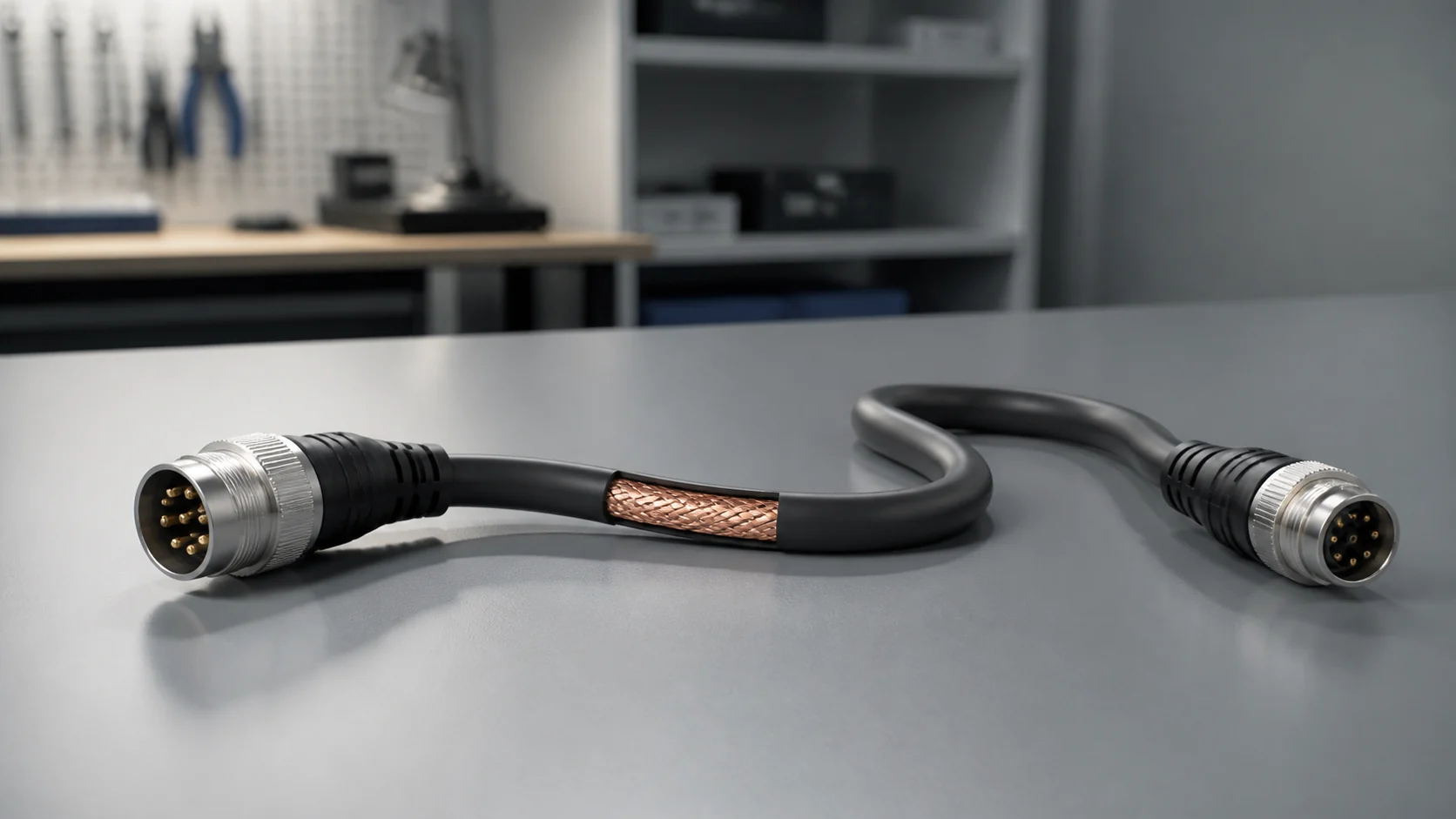
What does a shielded cable assembly manufacturer actually deliver?
A qualified manufacturer delivers a repeatable interconnect system: specified cable, connectors, contacts, shield treatment, strain relief, labels, workmanship criteria, and test records. Its responsibility is to convert the buyer’s drawing and EMC concept into controlled production instructions while identifying design details that are ambiguous, difficult to inspect, or likely to damage shielding performance.
The assembly may use an overall foil shield, a woven metallic braid, individually shielded pairs, a foil-and-braid combination, or another project-approved construction. The cable supplier establishes the raw cable’s properties. The assembly manufacturer then controls how much jacket is removed, how the shield is exposed, whether a drain wire is used, how the shield connects to a shell or grounding conductor, and how the transition is mechanically supported.
NASA’s public workmanship standard treats cable shielding as both a mechanical and electrical termination problem. It calls for shields to be mechanically terminated, such as by crimp rings or compression bands, and electrically grounded according to the manufacturing instructions, such as through a pigtail or conductive backshell. This is useful evidence of process principles, but it does not automatically become the governing requirement for a commercial project. The buyer must name the applicable standard and revision in the purchase documents.
A manufacturer should therefore ask questions before promising a design. What frequencies and coupling paths matter? Is the shield part of a chassis bond, circuit reference, or cable-to-cable continuation? Is termination required at one end, both ends, or through a project-specific network? Must the cable flex, twist, resist fluids, pass through a gland, or fit a restricted bend envelope? The equipment designer owns these system decisions; the manufacturer should make them buildable and testable.
Choose the shield construction from the interference and mechanical duty
Related OUKETECH resources: custom RF and coaxial cable assemblies.
Foil, braid, and combination shields solve different packaging and performance problems. A good selection starts with the application’s frequency range, required flexibility, cable diameter, termination method, and life-cycle environment. Buyers should avoid generic coverage claims unless the raw-cable datasheet and an assembly-level performance requirement explain how that number will be used.
This conceptual cutaway illustrates a possible foil-plus-braid construction. It is not a dimensional drawing and should not be used to release tooling or approve a bill of materials.
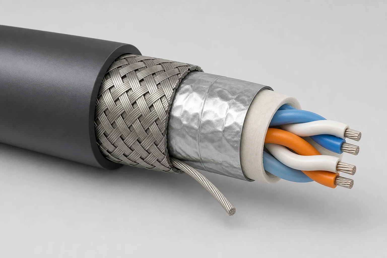
OUKETECH offers an excellent example of a product lineup: its aluminum foil shielding design emphasizes lightweight construction and a small cable diameter, whereas the composite “foil-plus-braid” structure combines both shielding layers to provide broader noise protection and superior flexibility. These descriptions apply to the manufacturer’s specific cable products rather than serving as universal performance benchmarks for all foil or braided shielding. This underscores why buyers should select specific, qualified cable models rather than expecting assemblers to infer performance based solely on generic shielding designations.
| Construction | Useful characteristics | Design and production questions | Typical reasons to reject a vague specification |
|---|---|---|---|
| Overall foil with drain wire | Thin, light, and relatively easy to terminate through the drain wire | Foil orientation, overlap, drain-wire size and location, bend duty, connector-shell method | “Foil shield” does not define cable part number, termination, or allowable drain-wire path |
| Overall braid | Flexible metallic network that can provide a robust circumferential bond when properly captured | Braid material, coverage from the cable datasheet, preparation length, ferrule or clamp, strand containment | A coverage percentage alone does not establish finished-assembly shielding effectiveness |
| Foil plus braid | Combines two shield mechanisms and can support a low-impedance circumferential connection | Layer order, drain-wire treatment, braid capture, cable diameter, backshell compatibility | More layers increase preparation complexity and do not compensate for a poor termination |
| Individually shielded pairs plus overall shield | Separates sensitive circuits and provides an overall barrier | Pair identity, individual drain wires, shield isolation, breakout geometry, grounding plan | Grounding every shield together may violate the system architecture or create unwanted coupling |
| Shielded twisted pair | Uses twisting to reduce loop pickup while the shield addresses external coupling | Pair lay, impedance requirement, connector pin assignment, untwist limit, shield termination | Substituting a different cable can change impedance, capacitance, flex life, and termination fit |
Cable geometry also affects assembly yield. A dense braid can be harder to comb back without broken strands. A foil may tear when the jacket strip process is poorly controlled. A large drain wire may not fit the intended backshell path. A stiff jacket may transfer bending force directly to the termination. These are design-for-manufacturability (DFM) issues that should be resolved in samples or a first-article build, not after volume production begins.
Why shield termination often matters more than shield coverage
The cable shield can only work as part of a continuous current path. Long exposed sections, uncontrolled pigtails, loose braid strands, paint or contamination at a bonding surface, and an insulating connector housing can add impedance or interrupt that path. For high-frequency applications, a short circumferential connection is often preferable when the connector system supports it.
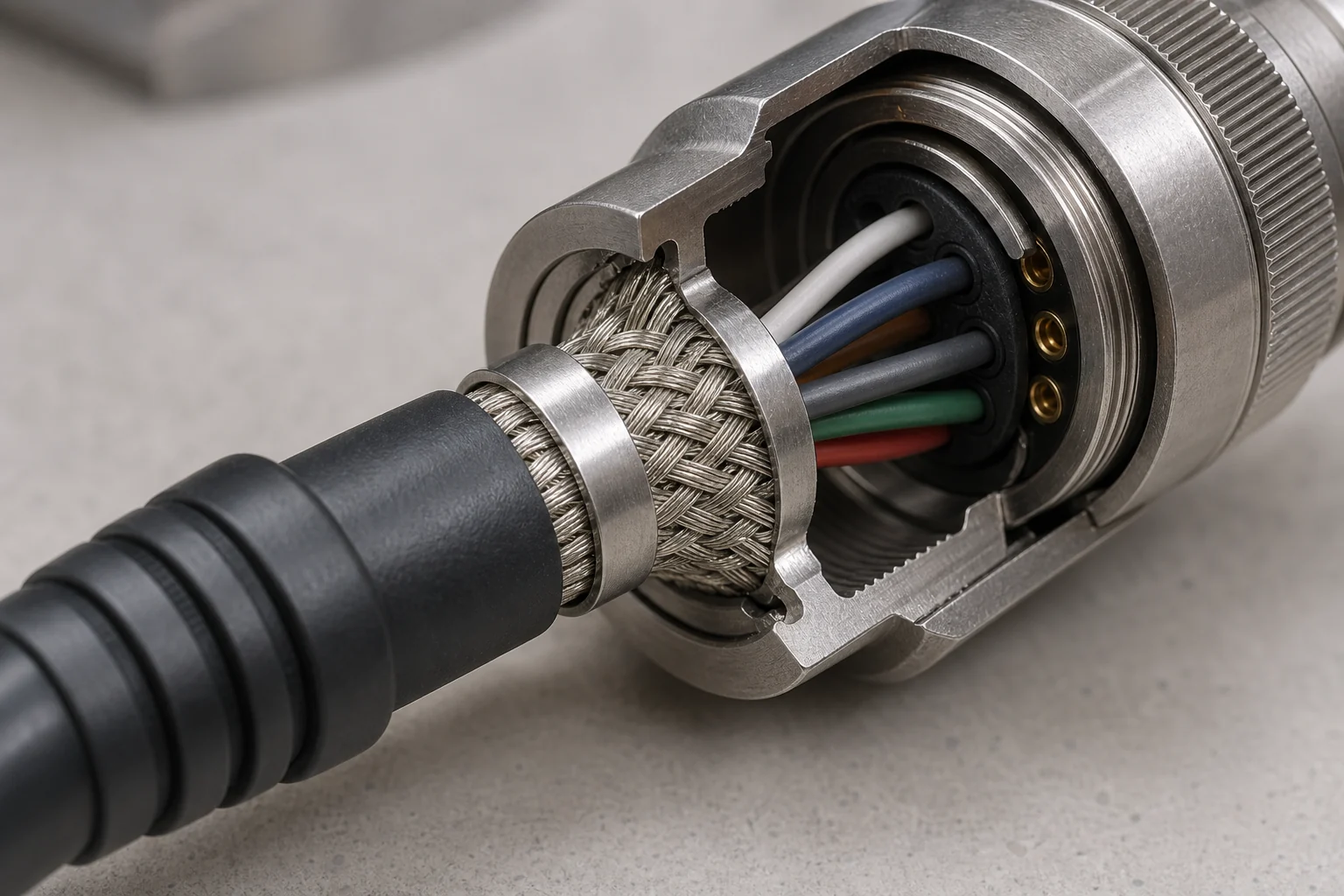
TE Connectivity describes a metal-shell M12 X-code connector with a 360-degree cable shield termination intended to support data transmission. TE also offers shield-splice products using a 360-degree metallic braid to maintain shield continuity. These are product-specific examples, but they show the engineering principle: termination hardware and cable preparation must be designed together.
The next image is a non-quantitative illustration of braid captured around a connector backshell. The project’s connector supplier instructions, cable dimensions, and approved tooling remain authoritative.
Not every assembly needs the same grounding scheme. One-end termination, both-end termination, chassis bonding, and circuit-reference connections behave differently across frequency and system topology. Ground loops, common-mode currents, safety bonding, cable length, enclosure seams, and the mating equipment all affect the result. The drawing should state the required connection rather than leave operators to decide during assembly.
The termination must also survive mechanical use. A braid bond is not a substitute for jacket strain relief. The finished connector should transfer pull, bend, and torsion loads through the intended clamp, boot, overmold, or backshell rather than through signal contacts or shield strands. If the cable moves repeatedly, the specification needs a bend radius, moving length, motion type, cycle profile, speed, acceleration, and environmental conditions. “High flex” alone is not an executable test requirement.
Turn the electrical design into controlled manufacturing instructions
Repeatable production depends on explicit preparation dimensions, approved tools, visual criteria, and a defined inspection frequency. The work instruction should separate conductor termination, shield termination, and mechanical strain relief because each has different failure modes. First articles should confirm that the selected cable, connector, ferrule, boot, and process fit together without damaging adjacent layers.
A practical manufacturing route normally includes incoming material verification, controlled cut and strip operations, conductor preparation, contact crimping or other approved termination, shield preparation, connector assembly, strain-relief installation, labeling, visual inspection, and electrical testing. The exact sequence depends on the connector design. Some shield clamps must be installed before contacts are inserted; some backshells require a defined assembly torque; overmolded versions need a validated pre-mold arrangement and material compatibility review.
IPC/WHMA-A-620 is the industry-consensus acceptance standard for cable and wire harness assemblies, according to WHMA. Buyers can use an applicable class and customer addenda to create a common workmanship language. However, citing the standard name without the revision, class, exceptions, and drawing hierarchy still leaves gaps. The contract should state which document wins if requirements conflict.
| Process point | Likely defect | How it can be detected | Prevention or control |
|---|---|---|---|
| Jacket stripping | Cut braid, torn foil, nicked insulation | Magnified visual inspection; first-piece section review when justified | Qualified stripping method, controlled blade or thermal settings, documented strip length |
| Braid preparation | Uneven coverage, loose strands, excessive unbraiding | Visual inspection against an approved sample and work instruction | Controlled comb-back or flare method; strand containment; correct ferrule size |
| Drain-wire routing | Drain wire omitted, pinched, too long, or connected to the wrong point | Visual inspection and shield-path continuity test | Drawing-defined route and termination; color or sleeve identification where appropriate |
| Contact crimping | Wrong crimp height, damaged strands, insulation in conductor crimp, weak pull strength | Crimp-height measurement, pull-force sampling, cross-section analysis when required | Calibrated applicator, approved terminal-wire combination, setup verification |
| Connector loading | Wrong pinning, backed-out contact, missing seal | Automated continuity map, visual inspection, contact-retention check as specified | Keyed fixtures, controlled pinout, secondary-lock verification |
| Shield-to-shell termination | Partial capture, contaminated bond surface, loose clamp | Visual inspection, low-resistance bond test with a defined method | Matched hardware, clean surfaces, controlled crimp or assembly process |
| Strain relief | Load transferred to shield or contacts, boot gap, overmold void | Pull/bend test, dimensional check, visual inspection | Correct jacket capture, material compatibility, validated fixture or mold |
| Final assembly | Open circuit, short circuit, shield-to-signal short | 100% continuity and isolation test against a programmed netlist | Locked test program, mating-interface control, traceable result handling |
The drawing should also control workmanship that ordinary netlist testing cannot see. An assembly can pass continuity while having a nearly severed braid, excessive conductor untwist, an incorrect strip length, weak jacket retention, or poor shield coverage at the connector. Visual and mechanical controls complement electrical testing; they are not optional duplicates.
Specify a test plan that matches the failure risk
Testing should distinguish basic wiring correctness from insulation safety, mechanical integrity, and shielding performance. Continuity can verify the intended net connections, while shorts testing detects unintended connections. Neither test alone proves broadband EMC performance. Buyers should define the method, limits, fixture, sampling level, and record format for every required characteristic.
The IEC describes IEC 62153-4-3 as a triaxial method for determining cable-shield surface transfer impedance by applying defined current and voltage conditions and measuring induced voltage. That is a specialized screening-effectiveness test, not a routine substitute for continuity testing on every production cable. Whether it applies depends on cable type, frequency range, product standard, and contractual requirements.
Likewise, hipot and insulation-resistance testing are not automatic requirements for every low-voltage signal assembly. Their voltage, dwell time, ramp, leakage or resistance limit, connected nodes, and test frequency must be compatible with the cable, connectors, embedded components, and end product. A supplier should not invent these limits. The equipment designer or governing product standard should provide them.
The image below represents a generic production test setup. Its blank screen intentionally avoids suggesting a real result or a universal pass limit.
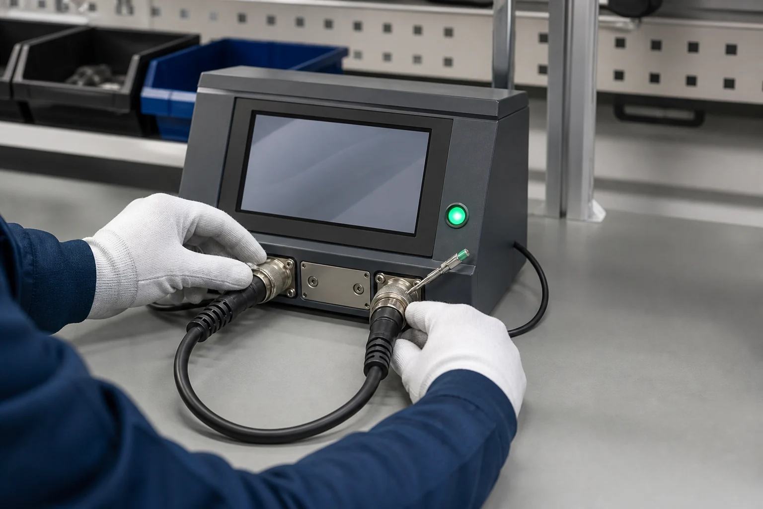
Conceptual electrical inspection scene; the released test specification and calibrated equipment define the actual verification.
| Test or inspection | What it can establish | What it does not establish | RFQ detail to provide |
|---|---|---|---|
| Visual workmanship inspection | Preparation, strand containment, hardware presence, routing, labels, and visible damage | Hidden electrical opens or frequency-dependent shielding | Standard/revision/class, customer criteria, magnification, approved sample |
| Continuity and shorts test | Correct conductor and shield net connections; absence of programmed cross-net shorts | Contact resistance under load, mechanical strength, broadband EMC | Netlist, test threshold, shield and shell nodes, 100% or sampled coverage |
| Shield-bond resistance | Resistance of a defined shield-to-shell or shield-to-pin path | Full transfer impedance or radiated susceptibility of the installed system | Probe points, current/method, limit, fixture compensation, sampling plan |
| Insulation resistance | DC isolation between defined conductors or shield nodes | Withstand capability under a higher stress or long-term environmental aging | Test voltage, dwell, minimum resistance, connected-node matrix |
| Dielectric withstand (hipot) | Survival and leakage behavior under a defined voltage stress | Signal integrity, EMC, or mechanical robustness | AC/DC waveform, voltage, ramp, dwell, leakage limit, exclusions |
| Pull, retention, or bend test | Mechanical robustness of contacts, shield termination, and strain relief under stated loading | Electrical behavior across the full application life | Load profile, direction, duration, acceptance criteria, sample size |
| Transfer-impedance or shielding test | Defined frequency-dependent behavior of a cable or assembly under the named method | Installed equipment immunity or emissions in every routing condition | Applicable standard, frequency range, fixture, sample definition, limit |
Build an RFQ that a manufacturer can quote without guessing
A strong RFQ gives the manufacturer enough information to identify material risk, process complexity, tooling, inspection time, and validation scope. It should distinguish mandatory requirements from preferences and future options. When a requirement is unknown, state who will decide it and at which design-review gate instead of leaving a blank that production may fill by assumption.
Include the following information:
- Application and electromagnetic environment: Nearby motors, variable-frequency drives, relays, RF transmitters, power converters, cable routing, enclosure interfaces, and the sensitive signal or data type.
- Released drawing and revision: Overall length, branch dimensions, datum scheme, tolerances, connector orientation, labels, pinout, mating connector, and change history.
- Bill of materials (BOM): Approved cable, connector, contact, backshell, ferrule, sleeve, boot, seal, overmold, and label part numbers, including approved alternates.
- Shield architecture: Overall or individual shields, foil or braid, drain-wire route, shield isolation, one-end or both-end connection, and connector-shell or grounding-pin mapping.
- Electrical requirements: Voltage, current, signal frequency or data protocol, impedance where relevant, contact-resistance limits, isolation requirements, and embedded components.
- Mechanical and environmental duty: Static or moving installation, minimum bend radius, torsion, pull, abrasion, oils, chemicals, UV, temperature, ingress, flame behavior, and installation constraints.
- Acceptance documents: Applicable workmanship standard, revision, class, customer addenda, conflict hierarchy, first-article requirements, and deviation process.
- Test plan: 100% versus sampled tests, methods, limits, fixtures, calibration expectations, raw-data needs, and certificate or report format.
- Commercial profile: Prototype quantity, annual volume, lot size, target schedule, forecast variability, service-parts horizon, packaging, shipping destination, and required traceability.
- Quality deliverables: Material certificates, approved-vendor evidence, inspection records, control plan, first-article report, change notification, and lot or serial traceability as the project requires.
Ask the supplier to return a structured DFM response. It should list drawing ambiguities, proposed material substitutions, tooling assumptions, special characteristics, inspection accessibility, test limitations, and open technical questions. A low unit price is not comparable when one quote excludes shield tooling, backshell hardware, test fixtures, or documentation.
How to evaluate a shielded cable assembly supplier
Evaluate the supplier with a sample build and evidence review, not marketing adjectives. A suitable manufacturer for one project may be unsuitable for another because connector systems, volumes, validation requirements, and motion duty differ. A documented process that matches the released design is more valuable than a long list of unbounded capabilities.
Use a scored review across engineering, sourcing, production, quality, and supply continuity:
| Evaluation area | Evidence to request | Strong response | Warning sign |
|---|---|---|---|
| DFM and requirement review | Marked drawing, open-issue log, risk list | Separates system decisions from manufacturing suggestions | Approves an ambiguous shield scheme without questions |
| Material control | Cable and connector datasheets, approved sources, substitution process | Links every critical characteristic to a controlled part number | Offers “equivalent cable” without electrical, mechanical, and dimensional comparison |
| Shield termination process | Work instruction excerpt, tooling list, first-piece criteria | Defines preparation, capture, bond point, and strain relief separately | Relies on operator judgment or a generic photo |
| Contact termination | Applicator control, crimp-height plan, pull-test plan | Uses the approved contact-wire-tool combination and measurable setup checks | Treats pull force as the only crimp-quality indicator |
| Electrical test | Netlist method, shield nodes, fixture plan, record sample | Explains what is 100% tested and what needs separate validation | Claims continuity proves EMC performance |
| Mechanical and environmental validation | Test specification, sample size, acceptance limits | Quotes only tests tied to the application and governing requirement | Promises universal flex, IP, temperature, or chemical performance without a defined build |
| Change and traceability | Revision control, lot records, deviation workflow | Can connect finished lots to released documents and controlled materials | Substitutes materials without written approval |
| Scale-up | Prototype-to-production control plan | Identifies manual prototype steps that need production tooling or validation | Assumes a hand-built sample transfers unchanged to volume production |
Before approval, compare the sample to the released drawing, inspect the shield transition, verify connector mating and keying, review the electrical result format, and exercise the cable in its intended route. If EMC risk is material, validate the assembly in the equipment or an agreed representative fixture. Cable-level shielding data cannot fully predict emissions or immunity after enclosure openings, connector interfaces, routing, and grounding are introduced.
Common sourcing mistakes and better decisions
Most shielded-cable sourcing failures begin with incomplete requirements rather than a single operator error. Buyers can reduce risk by naming the shield path, approved materials, mechanical duty, and evidence required before price negotiation. The following corrections turn vague requests into decisions that engineering, quality, and procurement can audit together.
- Replace “maximum EMI protection” with an applicable test method, frequency range, assembly configuration, and limit.
- Replace “braid shield, 90%” with an approved cable part number and finished termination requirements. Coverage describes raw-cable geometry, not the entire assembly.
- Replace “ground shield at both ends” with a drawing that identifies exact shield, shell, drain, chassis, and circuit-reference nodes.
- Replace “100% tested” with a test matrix listing continuity, shorts, shield bond, insulation, hipot, and functional checks that actually apply.
- Replace “high-flex cable” with a motion profile, bend radius, routing, cycle target, speed, temperature, and acceptance criterion.
- Replace “waterproof connector” with the mating condition, cable/backshell construction, required ingress test, and responsibility for validating the complete assembly.
- Replace “IPC compliant” with the exact standard, revision, class, customer addendum, exceptions, and document priority.
- Replace “same as sample” with a released drawing and BOM. A physical sample can supplement missing information but should not remain the sole production definition.
How OUKETECH can support a shielded cable assembly project
At the pre-production RFQ and DFM stage, our engineering team conducts one-to-one technical review for all project documents, including cable specifications, connector pinouts, shield architecture schemes, grounding logic, and mechanical environment parameters. We proactively identify ambiguous design details, untestable shielding structures, unreasonable strip dimensions, and mismatched termination solutions, and provide optimized DFM suggestions for foil-braid composite shielding, 360° circumferential shield termination, drain wire routing, and overmolded strain relief. This early intervention effectively avoids repeated sample revisions, EMC test failures, and cost waste caused by design defects in mass production.
In the prototyping and first-article validation phase, OUKETECH strictly executes IPC/WHMA-A-620 industry workmanship standards, customizing shield processing solutions tailored to different application scenarios. We precisely control key processes including jacket stripping, shield combing, strand containment, drain wire fixation, and backshell bonding to ensure complete shield continuity, uniform coverage, and low-impedance grounding path. For high-flex robotics, vibration-resistant industrial equipment, high-frequency medical instruments, and vehicle-mounted electronic systems, we differentiate shield termination and strain relief processes to match dynamic bending, torsion, and harsh environmental working conditions, ensuring both electrical EMC performance and long-term mechanical durability of the assembly.
For mass production, we build standardized, traceable production SOPs based on confirmed first-article standards. All raw cables, connectors, ferrules, and overmolding materials adopt approved sourcing management to avoid material substitution risks. We implement full-process quality control: 100% on-board continuity and short-circuit testing, shield bonding resistance inspection, insulation resistance and hipot verification according to project requirements, and dimensional & visual full inspection. Every batch of products is equipped with complete test reports, process records, and compliance certificates (RoHS, REACH), supporting customers’ product certification and factory audit demands
Beyond manufacturing, OUKETECH provides continuous project lifecycle support. We clarify unified workmanship judgment criteria for ambiguous technical requirements, formulate exclusive test plans matching the product’s EMI risk level and mechanical duty, and offer professional technical responses for shield grounding mode selection, one-end/two-end termination schemes, and shielding effectiveness optimization. Whether customers require low-MOQ R&D prototypes, medium-batch trial production, or long-term large-volume OEM orders, we maintain consistent workmanship standards and stable delivery cycles, helping customers accelerate project iteration and reduce overall sourcing and after-sales costs.
FAQ
What information does a shielded cable assembly manufacturer need to quote?
Provide a drawing and revision, BOM, cable and connector part numbers, pinout, overall and branch dimensions, shield-to-shell or shield-to-pin connections, grounding concept, electrical ratings, motion and environmental duty, workmanship standard, test limits, prototype quantity, annual volume, and required records. Mark unresolved design decisions instead of allowing silent assumptions.
Is foil or braid better for EMI shielding?
Neither is universally better. Foil can support a thin, light construction, while braid can add flexibility and a robust circumferential termination. A combined construction may address broader requirements but increases diameter and preparation complexity. Select a qualified cable from its datasheet and validate the finished assembly under the applicable EMC method and equipment configuration.
Does a drain wire replace a 360-degree shield termination?
Not automatically. A drain wire provides a convenient electrical connection to a foil shield, but its geometry differs from circumferential braid capture. The correct method depends on signal frequency, connector design, grounding architecture, mechanical duty, and governing requirements. The equipment designer should define the termination, and the manufacturer should follow controlled preparation instructions.
Should the cable shield connect at one end or both ends?
That is a system-level EMC and safety decision. Frequency, cable length, chassis design, ground potential differences, common-mode current paths, and equipment standards all matter. The assembly drawing should identify the exact connection at each end. A manufacturer should not choose one-end or both-end grounding as an undocumented shop-floor preference.
Does continuity testing prove the cable assembly is shielded correctly?
Continuity can show that a programmed shield path is electrically connected and that intended signal nets are correct. It does not establish transfer impedance, shielding effectiveness across frequency, mechanical durability, or installed-system EMC performance. Combine continuity with visual inspection, bond-resistance measurement, mechanical tests, and specialized shielding tests when the risk requires them.
When is 360-degree shield termination appropriate?
It is often considered when a metal connector and backshell are designed to capture the shield circumference and the application needs a short, controlled high-frequency path. Suitability still depends on compatible cable diameter, hardware, surface finish, strain relief, assembly instructions, and the equipment grounding concept. Use connector-manufacturer instructions and project validation.
What should be tested on every production assembly?
Many projects specify 100% continuity and shorts testing, but the correct production coverage is contractual. Shield-to-shell continuity, insulation resistance, or other tests may also be required. Destructive pull tests, cross-sections, environmental tests, and transfer-impedance measurements are normally sampled or qualification activities unless the governing specification states otherwise.
Can a manufacturer substitute a similar shielded cable?
Only through the buyer’s approved change process. A similar diameter or conductor count does not prove equivalence. Compare conductor resistance, capacitance, impedance, shield construction, jacket and insulation materials, temperature and voltage ratings, flex behavior, chemical resistance, flame requirements, connector fit, stripping behavior, availability, and required certifications before approval.