

Coaxial cable is used to carry radio-frequency, video, measurement, and other high-frequency electrical signals while controlling impedance and shielding the signal path. In business equipment, that means antenna feeds, telecom radios, automotive cameras and GNSS modules, machine-vision systems, medical instruments, broadcast hardware, and RF test equipment. The use case is only the starting point. Reliable sourcing depends on matching the complete cable assembly to the system frequency, impedance, loss budget, connector interface, routing, environment, and test plan.
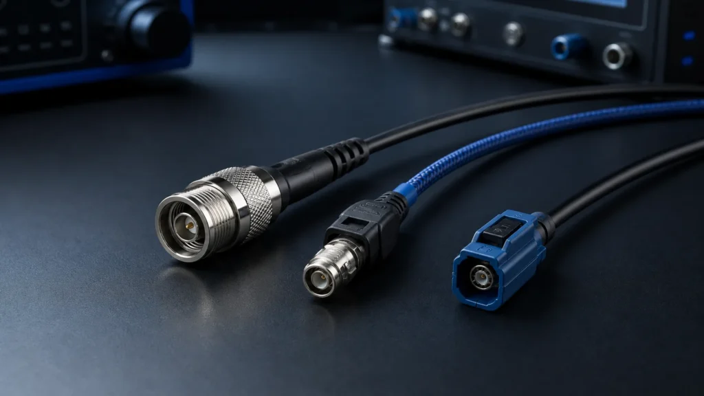
The practical buying question is not simply, “What is coaxial cable used for?” It is, “What does this signal path need the finished assembly to preserve?” A purchasing description such as “SMA cable, one meter” leaves the cable family, impedance, loss, shielding, connector gender, orientation, length reference, strain relief, and acceptance test unresolved. Those gaps turn into delays, substitutions, or an assembly that mates correctly but performs poorly in the equipment.
What makes coaxial cable different from ordinary wire?
Coaxial cable places one signal conductor inside a dielectric, then surrounds it with a concentric outer conductor and protective jacket. That controlled geometry creates a transmission line with a defined characteristic impedance. The outer conductor also provides the signal return path and shielding. Ordinary hookup wire can carry current, but it does not preserve a controlled RF path in the same way.
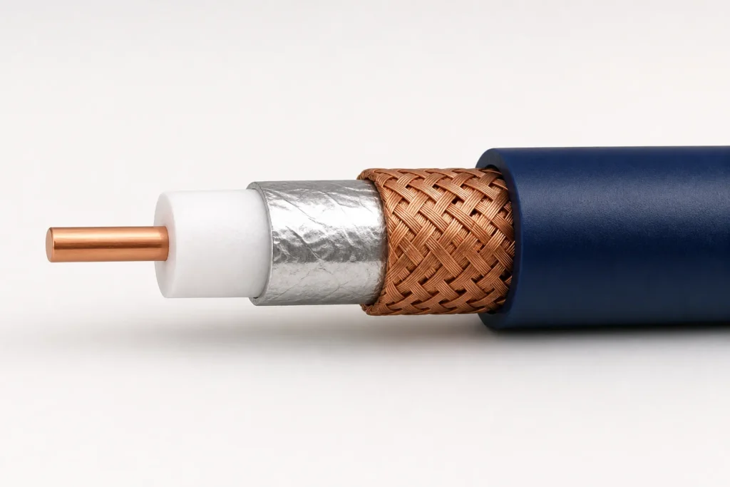
The layers work as a system:
- The center conductor carries the intended electrical signal. Its diameter, material, and plating influence resistance, flexibility, and loss.
- The dielectric holds the conductor in a stable position relative to the shield. Its material and geometry affect impedance and velocity of propagation.
- The outer conductor or shield completes the transmission line and limits electromagnetic coupling. It may use foil, braid, multiple shields, or a solid/semi-rigid construction.
- The jacket protects the electrical structure from abrasion, fluids, ultraviolet exposure, temperature, and handling, subject to the selected material rating.
Times Microwave Systems’ public selection guide explains that characteristic impedance depends on conductor geometry and the dielectric constant. It also identifies impedance, voltage standing wave ratio (VSWR), attenuation, power, shielding, flexibility, temperature, and environmental resistance as separate selection characteristics. A buyer therefore cannot infer system performance from an RG name or connector photograph alone.
What is coaxial cable used for in commercial and OEM equipment?
Coaxial cable is used wherever equipment must move an unbalanced high-frequency signal through a defined, shielded path. Common B2B applications include radios and antennas, vehicle camera and connectivity systems, industrial vision and sensing, medical instrumentation, laboratory measurement, and broadcast video. Each application imposes a different combination of frequency, loss, shielding, packaging, motion, and validation requirements.
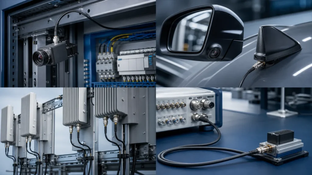
| OEM application | What the coaxial path carries | Typical buying priorities | Details that must be confirmed |
|---|---|---|---|
| Telecom radios and antennas | Transmit and receive RF energy | Low insertion loss, impedance control, shielding, outdoor durability | Frequency band, power, length, connector interface, sealing, return-loss or VSWR limit |
| Automotive cameras, GNSS, telematics and antennas | Video, serialized data, positioning and RF signals | Compact keyed connectors, retention, routing, vibration and temperature performance | Protocol, cable family, FAKRA or specified interface, key code, orientation, sealing, vehicle validation requirements |
| Industrial machine vision and sensing | Camera, sensor or antenna signals near electrically noisy machinery | EMI control, abrasion resistance, flex duty, compact routing | Static or moving installation, bend radius, oils, enclosure entry, mating cycles, test bandwidth |
| Medical and laboratory instruments | Low-level measurement, imaging, RF excitation or detector signals | Noise control, repeatable connections, cleanability and documentation | Equipment-level safety requirements, flex/cleaning duty, approved materials, traceability, electrical acceptance plan |
| RF test and measurement | Stimulus and response signals between instruments and devices under test | Stable loss, return loss, phase behavior and repeatable mating | Full frequency range, reference planes, connector torque, calibration approach, phase/length requirement |
| Broadcast, professional video and surveillance | Baseband or modulated video and related signals | 75-ohm compatibility, routing density, connector retention | Interface standard, bandwidth, cable length, BNC or other connector version, installation environment |
Telecom, wireless infrastructure and antenna feeds
Telecom equipment uses coaxial assemblies between radios, antennas, filters, combiners, test ports, and cabinet interfaces. The buyer’s main concern is usually not whether the cable can conduct a signal. It is whether the link stays inside the allowed insertion-loss and reflection budget across the full operating band and installed environment.
Longer routes and higher frequencies generally make attenuation more important. Connector transitions, adapters, bends, and workmanship can add reflection or loss. Outdoor routes introduce water ingress, ultraviolet exposure, temperature cycling, and mechanical load. An RFQ should state the installed length, maximum frequency, power, impedance, connector interfaces, routing, and required assembly-level evidence rather than asking only for a “low loss coaxial cable.”
Automotive cameras, GNSS, telematics and infotainment
Modern vehicles use coaxial links for cameras, sensors, antennas, global navigation satellite system (GNSS) receivers, telematics control units, cellular connectivity, and some high-speed serialized data paths. Packaging density, keyed mating, vibration, sealing, routing, and manufacturing repeatability can matter as much as the nominal bandwidth.
TE Connectivity’s FAKRA system page identifies cameras, sensors, GNSS, cellular, Wi-Fi/Bluetooth, V2X, and infotainment among its automotive RF applications. The page describes that specific connector family as supporting RF performance up to 6 GHz; this is a product-family statement, not a universal rating for every automotive cable assembly.
For quotation, specify the exact connector manufacturer and part number, housing key, cable type, straight or right-angle orientation, finished-length reference, retention features, routing envelope, sealing requirement, and applicable customer or vehicle test specification. “Blue FAKRA cable” is not an adequate BOM because color and keying do not fully define terminal, housing, cable, or process compatibility.
Industrial automation, machine vision and connected equipment
Industrial equipment uses coaxial cable for machine-vision cameras, RF identification, wireless gateways, sensors, legacy video, and instrument connections. The environment can combine motor drives, contactors, power converters, oil, abrasion, vibration, tight cable tracks, and repeated maintenance. A catalog patch lead may work on a bench yet fail once it is routed through the machine.
Separate electrical and mechanical duty in the specification. Define the signal band and impedance, then state whether the cable is static, occasionally moved, or continuously flexed. Add minimum bend radius, torsion, travel, cycle profile, temperature, fluid exposure, enclosure interface, and mating frequency. If the assembly enters a sealed housing, the gland, bulkhead, overmold, and cable jacket must be reviewed together. OUKETECH’s overmolded cable assembly capabilities are relevant when strain relief, sealing, or a project-specific connector transition must be integrated into the finished lead.
Medical equipment and precision instrumentation
Medical and precision instruments may use coaxial paths for imaging, patient-monitoring signals, probes, RF energy, detector outputs, or internal module connections. The correct design depends on the equipment architecture. A generic “medical-grade coax” label does not establish safety, cleanability, biocompatibility, sterilization compatibility, leakage limits, or regulatory suitability.
The device manufacturer should identify the approved materials, intended cleaning or sterilization process, flex duty, voltage and frequency, shielding approach, traceability needs, and governing equipment-level verification. The cable assembler should build to those controlled requirements and document any proposed change. Procurement teams should reject broad medical claims that are not tied to the released assembly and device risk file.
RF test, measurement and laboratory systems
Test systems use coaxial assemblies between signal generators, analyzers, fixtures, switches, antennas, and devices under test. Here, a cable is part of the measurement path. Handling can change loss or phase, poor mating can damage interfaces, and an undefined adapter can move the reference plane.
For ordinary bench connectivity, a catalog assembly may be sufficient. Phase-matched sets, low-loss links, repeated-flex measurement leads, or fixtures with stable electrical length require a more specific request. State the frequency range, insertion-loss and return-loss limits, phase or delay requirement, connector interface, mating-cycle expectation, routing, identification, and whether individual serialized data is required. Do not accept “VNA tested” without the vector network analyzer test band, calibration method, reference planes, fixture treatment, acceptance limits, and report format.
Broadcast, professional video and surveillance
Broadcast and professional video commonly use 75-ohm coaxial signal paths, while many wireless and microwave systems use 50-ohm paths. The important rule is to match the cable, connector, source, and load to the equipment architecture. A BNC connector can exist in both impedance families, so visual similarity does not prove electrical compatibility.
High-density racks add routing and serviceability concerns. Specify cable diameter, allowable bend, connector coupling, panel spacing, color or label identification, and maximum assembly loss across the required video bandwidth. Factory-built assemblies can reduce the variability of field stripping and connector installation, especially when many identical channels must be commissioned on a fixed schedule.
How do 50-ohm and 75-ohm coaxial cable uses differ?
Fifty-ohm coax is common in RF, microwave, wireless, antenna, and test systems, while 75-ohm coax is common in cable television, broadcast video, and video distribution. These are conventions, not permission to choose by industry name alone. The correct impedance is the one specified by the source, load, connector system, and overall signal-path design.
An impedance discontinuity reflects part of the signal. The finished assembly includes the cable, connector transition, adapters, and mating interfaces, so every element matters. Times Microwave notes that connectors and the connector-to-cable interface can be major contributors to reflection. It recommends considering factory-assembled and tested cables where VSWR is critical.
Do not substitute 50-ohm and 75-ohm parts because the connectors happen to mate. The assembly may pass a continuity test and still create unacceptable return loss, waveform distortion, or link margin. If the equipment documentation is unclear, ask the design authority to identify the system impedance and acceptance method before releasing the purchase order.
How should an OEM choose a coaxial cable assembly?
Choose the assembly from the system outward: impedance and frequency first, then loss, power or voltage, shielding, connector interfaces, routing, environment, mechanical life, and validation. A named cable family helps only when the exact manufacturer part number and revision are controlled. The finished assembly must be evaluated, because termination and routing can change performance.
| Decision input | What to send the supplier | Why it changes the design or quote | Weak specification to avoid |
|---|---|---|---|
| Signal and impedance | Signal type, 50/75/other ohms, source and load interfaces | Controls cable and connector compatibility | “Standard coax” |
| Operating band | Minimum and maximum frequency, required bandwidth | Loss and reflection are frequency-dependent | “High frequency” |
| Electrical limits | Insertion loss, return loss or VSWR, power/voltage, phase or delay when relevant | Defines cable size, length, connector transition, and test scope | “Low loss, good VSWR” |
| Cable and connectors | Approved manufacturer part numbers, gender, polarity, key, orientation and mounting | Prevents visually similar but incompatible substitutions | Photo or family name only |
| Length and routing | Finished-length datum, tolerance, bend radius, formed shape and installation access | Affects loss, fit, strain and repeatability | “About one meter” |
| Environment | Temperature, fluids, UV, moisture, vibration, altitude and cleaning | Drives jacket, sealing, plating and qualification choices | “Industrial grade” |
| Mechanical duty | Static/flex/torsion profile, cycles, pull load and mating cycles | Drives cable construction and strain relief | “Flexible cable” |
| Inspection and tests | Method, limits, frequency band, sampling, fixtures, calibration and report format | Determines equipment time, fixtures, data and price | “100% tested” |
| Commercial demand | Prototype quantity, annual volume, lot size, forecast and target dates | Drives material packs, tooling, process automation and lead time | Unit price request without volume |
Start with the signal budget, not the connector catalog
A connector name is not a performance specification. Begin with the system frequency, impedance, allowable insertion loss, and reflection limit. Then allocate margin across cable length, connectors, adapters, and installation. The Amphenol RF coaxial cable guide illustrates how cable options vary by impedance, dielectric, outside diameter, and shield construction. Use the approved cable datasheet for the actual design.
Treat length, bending and strain relief as electrical inputs
Extra length adds loss and occupies space. An overly tight bend can disturb the cable geometry, while repeated motion can change performance or damage the conductor and shield. The drawing should define the length datum and tolerance, connector clocking, formed route where necessary, and the intended load path through the clamp, boot, backshell, or overmold.
Control the entire connector definition
An executable BOM identifies manufacturer part numbers for connectors, contacts, housings, ferrules, boots, and cable. It also defines gender, polarity, orientation, bulkhead hardware, panel thickness, keying, plating, and mating interface. For more detail, use OUKETECH’s coaxial connector selection guide as a starting point, then verify the chosen supplier datasheets.
Specify evidence that matches the risk
Continuity and open/short testing confirm basic connectivity. They do not prove insertion loss, return loss, VSWR, phase, shielding effectiveness, environmental survival, or long-term flex performance. Those characteristics need defined methods and limits. The quote should say which tests are performed on every unit, which are sampled, which require a first article, and which are outsourced or unavailable.
When does a custom coaxial cable assembly make business sense?
A custom coaxial cable assembly makes sense when standard leads cannot meet the required length, connector combination, orientation, routing, strain relief, environment, identification, testing, documentation, or supply-control needs. Customization should remove project risk, not add decorative options. The economic case is strongest when a controlled finished lead prevents field termination, installation errors, rework, downtime, or repeated supplier substitutions.
Common triggers include:
- A connector pair or cable family is unavailable as a standard catalog lead.
- The enclosure needs a right-angle, bulkhead, keyed, sealed, or compact interface.
- The installed loss budget does not tolerate unnecessary cable length or adapters.
- The assembly must follow a formed route or defined connector clocking.
- The application needs an overmold, boot, protective sleeve, label, serialized ID, or installation kit.
- The buyer needs build-to-print revision control, approved substitutions, lot traceability, or test records.
- Prototype, small-batch, high-mix, or repeat high-volume demand must use the same released design.
OUKETECH’s main RF and custom coaxial cable assembly manufacturing page is the commercial destination for these requirements. It covers build-to-print review, cable and connector definition, prototypes, low-volume and repeat production, and project-specific inspection or RF testing. Capability, test method, sampling, equipment, and report format must still be confirmed in the quotation for the exact part.
What should a buyer ask a coaxial cable assembly supplier?
Ask for evidence that the supplier can translate your released specification into repeatable cable preparation, termination, inspection, testing, and change control. A convincing answer identifies assumptions and open issues before quoting. A weak answer promises universal performance without knowing the frequency band, cable part number, connector interface, route, or acceptance limits.
| Evaluation area | Evidence to request | Strong response | Warning sign |
|---|---|---|---|
| Requirement review | Marked drawing, BOM review and open-question list | Separates customer design decisions from manufacturing recommendations | Quotes from a photo without recording assumptions |
| Material control | Supplier datasheets, approved sources and substitution process | Controls exact cable and connector part numbers by revision | Uses “equivalent” cable without dimensional and RF comparison |
| Termination process | Preparation dimensions, tooling and first-piece criteria | Links cable group, connector, strip dimensions and assembly method | Relies on operator judgment alone |
| Mechanical control | Length datum, clocking, strain relief and routing fixture plan | Explains how fit and load path will be reproduced | Treats nominal length as the only mechanical requirement |
| Electrical testing | Netlist and RF test plan with methods, limits and sampling | States exactly what every unit and sample will prove | Claims continuity proves RF performance |
| Traceability and change | Revision, lot, deviation and end-of-life workflow | Requires written approval before critical substitution | Changes materials after approval without notification |
| Scale-up | Prototype-to-production plan and capacity assumptions | Identifies which manual steps need fixtures or process validation | Assumes a hand-built sample transfers to volume unchanged |
Price comparisons are meaningful only when scope is aligned. One quote may include named connectors, controlled tooling, 100% open/short testing, RF sampling, labels, protective caps, and export packaging. Another may exclude all of them. Procurement should normalize the BOM, test plan, tooling, non-recurring engineering, MOQ, lead time, documentation, packaging, and freight before selecting a supplier.
How OUKETECH turns application requirements into a quote
OUKETECH supports OEM buyers who need a custom assembly built to an approved drawing, BOM, sample, or controlled requirement package. The useful starting point is a complete technical file, not a generic request for a “recommended coax cable.” Engineering review can then address cable-and-connector compatibility, finished length, routing, strain relief, process feasibility, inspection access, test scope, material availability, and production assumptions.
The project can be reviewed for prototypes, small batches, high-mix demand, scheduled repeat orders, or high-volume production. The quote should separate sample approval from production release and identify any tooling, fixtures, material pack quantities, or test setup. OUKETECH will confirm project-specific MOQ, lead time, available tests, sampling, documentation, and commercial terms rather than imposing one answer on every design.
For a useful response, send:
- Released drawing and revision, or an authorized sample for replication.
- BOM with cable and connector manufacturer part numbers and approved alternates.
- Impedance, operating frequency range, power or voltage, and the assembly loss/reflection limits.
- Finished-length datum, tolerance, connector orientation, bulkhead details, and routing constraints.
- Temperature, vibration, flex, fluids, sealing, UV, cleaning, or other environmental requirements.
- Inspection and test methods, limits, sampling, calibration expectations, and report format.
- Prototype quantity, annual forecast, lot size, target dates, packaging, labels, and ship-to country.
If some inputs are unresolved, identify the design owner and decision date. That gives the supplier a basis for a DFM response without turning assumptions into hidden production requirements.
FAQ: Coaxial Cable Uses and Sourcing
Is coaxial cable used only for television and internet?
No. Television and cable broadband are familiar uses, but OEM equipment also uses coaxial cable for antennas, radios, automotive cameras, GNSS, telematics, industrial vision, medical instruments, laboratory test systems, broadcast video, and many other RF or high-frequency signal paths. The cable construction and connector system must match each application.
Can I use a 50-ohm coaxial cable in a 75-ohm system?
Do not substitute it without an engineered matching plan. A 50-ohm cable in a 75-ohm signal path creates an impedance discontinuity and reflections. The assembly may still pass continuity while failing the equipment’s return-loss, waveform, or link-margin requirements. Match cable, connectors, source, and load to the specified system impedance.
Does a thicker coaxial cable always perform better?
No. A larger cable may reduce loss or increase power handling within a product family, but it can also increase weight, bend radius, connector size, and installation force. Cable geometry, dielectric, conductor, shield, frequency, length, and environment all matter. Select from the approved datasheet and verify the finished assembly against the system requirements.
What is the difference between coaxial cable and RF cable?
Coaxial describes a concentric cable construction. RF describes a radio-frequency application. Many RF cables are coaxial, but not every coaxial cable is suitable for every RF band, power level, environment, or connector. Buyers should specify the actual operating band and acceptance limits instead of treating the terms as interchangeable grades.
What information is needed for a custom coaxial cable quote?
Provide the drawing and BOM, cable and connector part numbers, impedance, frequency band, finished length and tolerance, loss or reflection limits, routing and environmental requirements, test plan, sample quantity, annual volume, target dates, packaging, and destination. OUKETECH can identify open questions during review, but the design authority must approve final requirements and substitutions.
Request a custom coaxial cable assembly quote
A coaxial cable is valuable because it preserves a controlled signal path. A custom assembly is valuable when it preserves that path and fits the equipment, survives the environment, arrives with the right evidence, and can be built again under revision control.
Send OUKETECH your coaxial cable drawing, BOM, connector part numbers, frequency band, impedance, length, routing, volume, and test requirements for a DFM review and project-specific quotation. For available cable families, connector options, application coverage, and manufacturing workflow, start with the RF & Coaxial Cable Assembly Manufacturer page.