

A wire harness drawing should let a supplier answer three questions from the released files alone. What connects to what? Where does each branch, connector, and clip need to land? What will the buyer measure or test before accepting the assembly?
The most important considerations when drawing a wire harness are connector orientation, pin-to-pin connections, finished dimensions, component compatibility, and acceptance criteria. For OEM engineers and sourcing teams, documenting these details before an RFQ helps suppliers quote the same build and gives the first-article inspector a clear basis for approval.
What Goes on a Wire Harness Assembly Drawing?
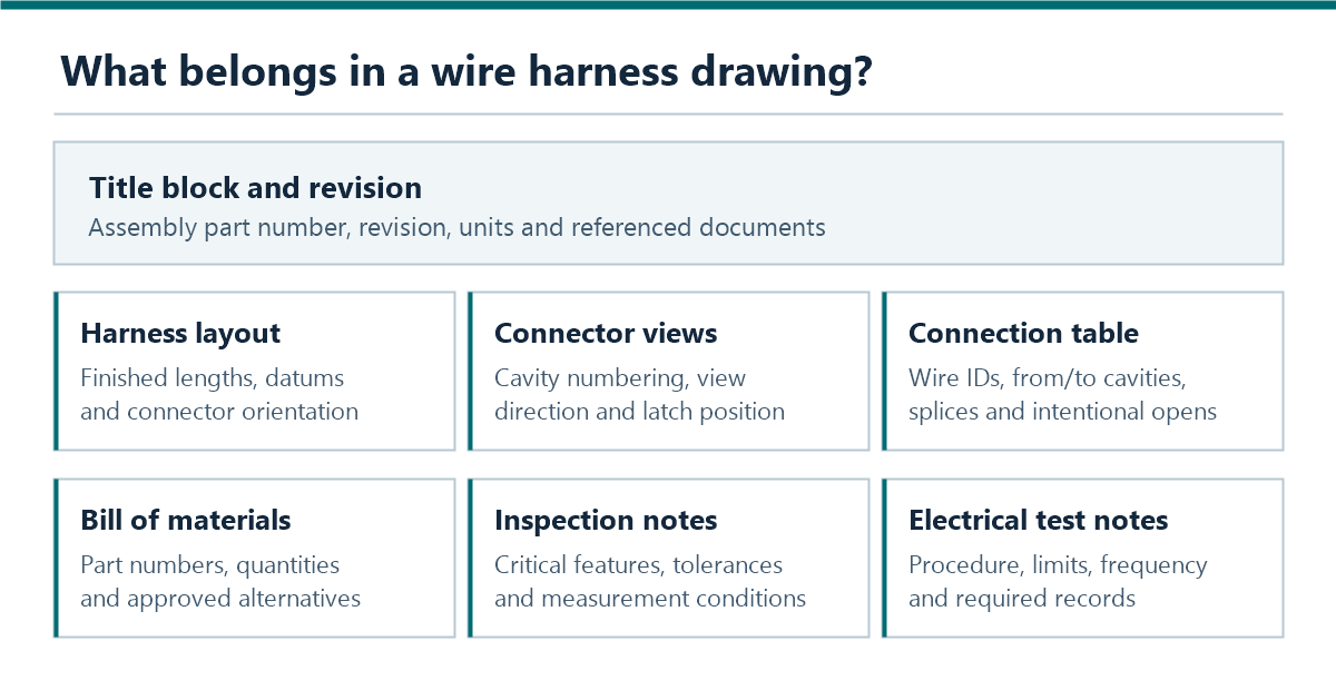
A supplier needs the electrical definition and the physical layout. The wiring diagram or connection table defines circuits and cavity assignments. The harness layout defines branches, finished dimensions, connector orientation, and the positions of clips, labels, and protective coverings. The drawing can include the tables directly or reference separately controlled files by document number and revision.
| Drawing element | What to specify before supplier release |
|---|---|
| Title block | Assembly part number, drawing revision, units, and referenced documents |
| Connector views | Designators, view direction, cavity numbering, keying or latch position, and required clocking |
| Connection table | Wire ID, from/to cavities, circuit name, wire specification, and splices or intentional opens |
| Harness layout | Finished trunk and branch lengths, measurement datums, tolerances, and measurement condition |
| Bill of materials | Manufacturer and part numbers, quantities, approved alternatives, and controlled material specifications |
| Inspection and test notes | Critical dimensions, required test procedures and limits, inspection frequency, and records |
For the routing and component choices that precede the drawing, see our custom wire harness design guide.
1. Show Connector Views and Cavity Numbers
Label each connector with a designator such as J1 or J2. State whether the drawing shows the mating face or wire-entry side, then identify an orientation feature such as a latch or polarization key. A cavity pattern can appear reversed when viewed from the opposite side. Check the numbering against the connector manufacturer's documentation for the exact housing part number.
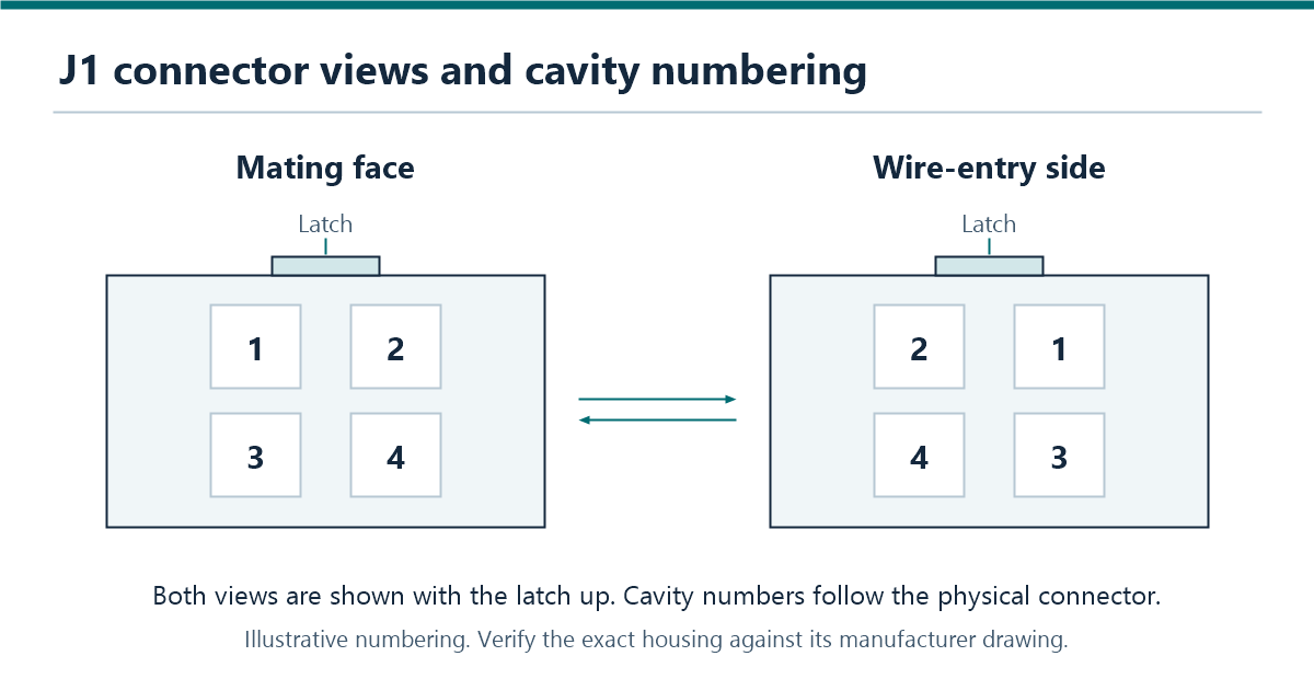
Show the required clocking of right-angle exits, backshells, and keyed attachments relative to the connector. Mark unused cavities and identify any plugs or seals required by the connector system. Where variants share a housing, identify how the operator can distinguish the applicable cavity population.
2. Make the Pinout Traceable by Wire ID
The wire harness pinout table should connect every conductor to named endpoints. Use the same wire IDs in the drawing, connection table, and inspection files. Include the circuit name, both connector cavities, and a reference to the wire specification. Color helps identify a wire on the bench, especially when paired with an ID that remains stable across revisions.
For multiple wires sharing a net, identify the splice and its branches or explicitly specify an approved multi-wire termination. If the build includes shields and drain wires, show the termination at each end and any intentionally insulated end. List intentional connections and unused cavities so the test program reflects the released circuit definition.
3. Set Branch Lengths and Tolerances on the Wire Harness Drawing
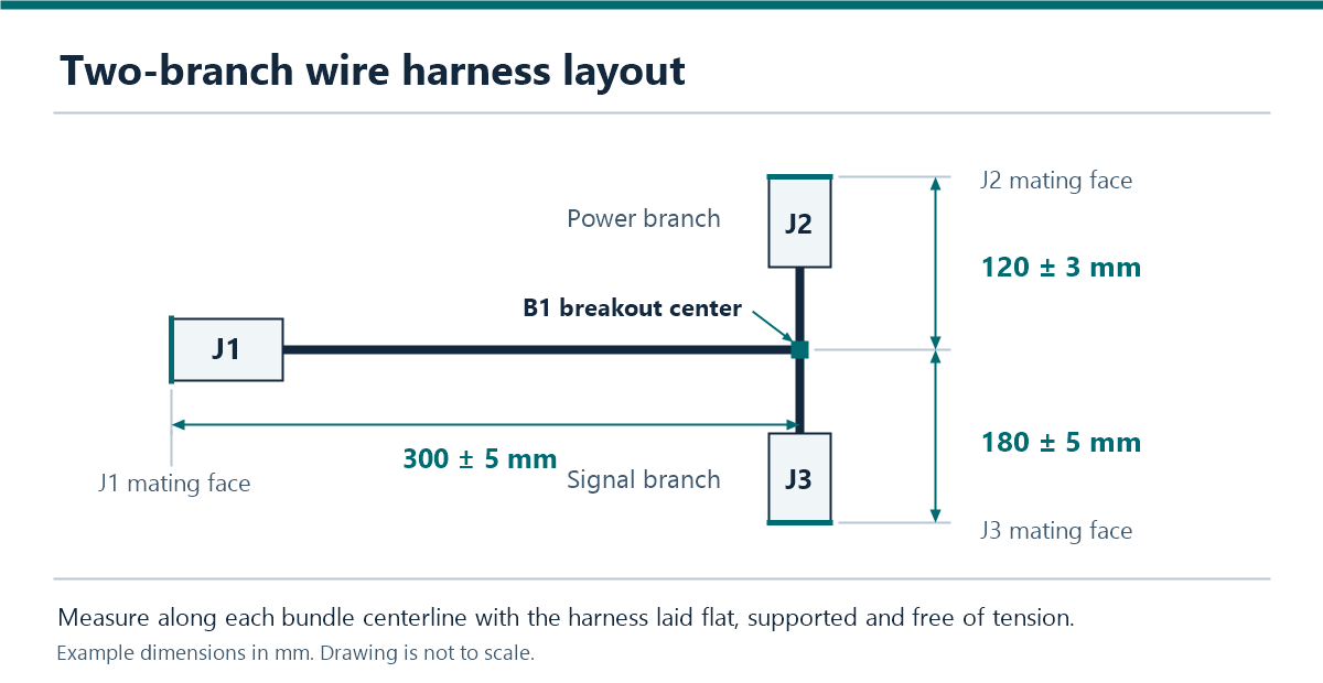
Give each critical branch length a named start and end point, a tolerance, and a measurement condition. A dimension might run along the bundle centerline from breakout B1 to the J2 mating face with the harness laid flat, supported, and free of tension. Identify dimensions verified in a formed fixture when the assembly needs to hold a defined shape.
Keep cut lengths in the controlled cut list or wire schedule. Finished dimensions and cut lengths serve different purposes. Terminal insertion, connector geometry, and routing inside a bundle all affect the length of wire required to achieve an overall assembly dimension.
Show clip locations and orientation, label placement, sleeving boundaries, and strain relief as applicable. Base critical tolerances on the equipment fit and the inspection method. If several dimensions can stack up at an installation interface, review them together with the supplier before setting the manufacturing tolerances.
4. Match the BOM to the Connector System
The wire harness bill of materials should identify the housing, terminals, seals, plugs, and locks individually when they are separate purchased items. For each wire, specify the gauge or cross-section and the required conductor and insulation construction. Confirm that the selected terminal supports the conductor and that the insulation outside diameter fits the applicable insulation crimp and seal ranges.
State where substitutions require engineering approval, and record accepted alternatives in the controlled BOM or an approved deviation. A supplier's quote should identify the components it priced and any sourcing assumptions. For a build sequence that connects these callouts with fabrication and inspection, see the wire harness assembly process guide.
5. Define Wire Harness Inspection and Test Requirements
Reference the released pinout or netlist for continuity and unintended-connection checks. Define the test procedure or its document reference, any required limits, inspection frequency, and records. For dimensional inspection, identify critical features and the measurement setup. If the project requires insulation resistance, dielectric withstand, or functional testing, use a project-approved procedure that addresses any sensitive components present in the assembly.
When the purchase specification invokes IPC/WHMA-A-620, identify the applicable revision and class. Keep project-specific electrical limits and fit checks in the drawing or referenced specifications. See our guide to IPC/WHMA-A-620 requirements for harness assemblies.
Wire Harness Drawing Example for a Two-Branch Assembly
This illustrative example shows the relationship between a layout, the pinout, and a first-article check. The dimensions and part references demonstrate drawing notation.
Layout. A four-cavity connector J1 feeds two branches at breakout B1. J2 is the power branch and J3 is the signal branch. Connector face views identify each cavity by number and show the latch at the top.
| Finished dimension | Example callout |
|---|---|
| J1 mating face to B1 breakout center | 300 ± 5 mm |
| B1 breakout center to J2 mating face | 120 ± 3 mm |
| B1 breakout center to J3 mating face | 180 ± 5 mm |
The example drawing measures each distance along the associated bundle centerline with the harness supported, laid flat, and free of tension. The connector datum is where the bundle centerline, extended as needed, intersects the mating-face plane.
| Wire ID | From | To | Function | BOM reference |
|---|---|---|---|---|
| W01 | J1-1 | J2-1 | Power feed | Wire item 10 |
| W02 | J1-2 | J2-2 | Power return | Wire item 10 |
| W03 | J1-3 | J3-1 | Signal | Wire item 11 |
| W04 | J1-4 | J3-2 | Signal return | Wire item 11 |
At first article, the inspector verifies all four endpoint pairs, checks for unintended connections between the four nets, and measures the three finished lengths using the stated datums. If the layout calls for clocking or clip orientation, record those checks on the same inspection record. For example, replacing “J2 branch length 120 mm” with the full B1-to-mating-face callout gives the supplier and inspector the same measurement endpoints.
Wire Harness Drawing Checklist Before Release
- Confirm the drawing, BOM, pinout, and test specification belong to the same approved release.
- Check every connector view against the manufacturer's cavity numbering and identify intentional empty cavities.
- Verify that finished dimensions, tolerances, and measurement conditions can be reproduced at first article.
- Confirm terminal, wire, and seal compatibility and mark any supplier substitutions that require approval.
- Ask the supplier to list open questions, quote assumptions, and the tooling or fixture needs that affect price or schedule.
- Record the approved first-article revision and any deviations before releasing a production order.
If a connector, wire, route, or pin assignment changes after approval, identify the affected BOM, tooling, fixtures, test program, inventory, and open orders. State when the new revision takes effect and whether the change requires another first article or an agreed subset of checks.
Frequently Asked Questions
What wire harness drawing details does a supplier need for a quote?
A supplier can use a schematic for an initial review if you also describe the application and expected quantities. For a comparable production quote, provide finished dimensions, connector and wire part numbers, the test scope, and any open decisions the supplier should price as assumptions. See the custom wire harness quotation requirements.
What is the difference between a wiring diagram and a wire harness drawing?
A wiring diagram describes the connections between circuits or devices. A wire harness drawing combines the physical assembly definition with the pinout and build requirements, either directly or through referenced documents. A manufacturer uses those details to build and inspect the assembly.
What should a wire harness drawing template include?
Start with a title block, a layout view, connector face views, a connection table, a BOM reference, and inspection notes. Add fields for shield termination, splices, labels, and fixtures where the assembly requires them. For a repeat build, identify the exact revision of each controlled reference.
Request a Quote for Your Wire Harness Drawing
For custom wire harness manufacturing, send OUKETECH your current drawing, BOM, pinout, prototype quantity, expected production volume, and required inspection records. Flag dimensions or materials that are still open so the quotation can reflect the work needed to resolve them.